Supercharge Your Innovation With Domain-Expert AI Agents!

Auxiliary tightening device for automobile parts production

A technology for auto parts and skateboards is applied in the field of auxiliary tightening devices for auto parts production, which can solve the problems of manpower consumption and low efficiency, and achieve the effect of improving assembly efficiency and saving manpower.

Active Publication Date: 2020-02-14
ANQING JIAN AUTO PART FORGING & ROLLING
View PDF7 Cites 0 Cited by
  • Summary
  • Abstract
  • Description
  • Claims
  • Application Information

AI Technical Summary

Problems solved by technology

[0003] The purpose of the present invention is to solve the problem of labor-intensive and low efficiency in the prior art, and propose an auxiliary tightening device for the production of auto parts

Method used


Image

  • Auxiliary tightening device for automobile parts production
  • Auxiliary tightening device for automobile parts production
  • Auxiliary tightening device for automobile parts production

Examples


Embodiment 1

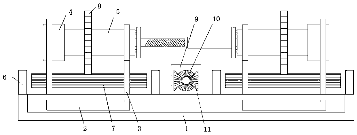
[0025] refer to Figure 1-4 , an auxiliary tightening device for the production of auto parts, comprising a device base 1, the device base 1 is provided with a horizontal chute, and a slide plate 2 is slidably connected in the horizontal chute, two slide plates 2 are arranged side by side, and the top sides of the slide plates 2 are Two rotating brackets 3 are fixedly arranged, and the top sides of the two rotating brackets 3 all extend to the vertical top of the device base 1, and the rotating frame is respectively provided with a vertical ring 4 and an outer cylinder 5, and one end of the outer cylinder 5 is connected to the vertical One side of the straight circular ring 4 is fixedly welded coaxially, the outside of the cylinder body of the outer cylinder 5 is fixedly covered with a transmission gear ring 8, the top side of the device base 1 is fixedly provided with a rotating seat 6, and the rotating seat 6 is connected with a transmission gear in rotation Column 7, transm...

Embodiment 2

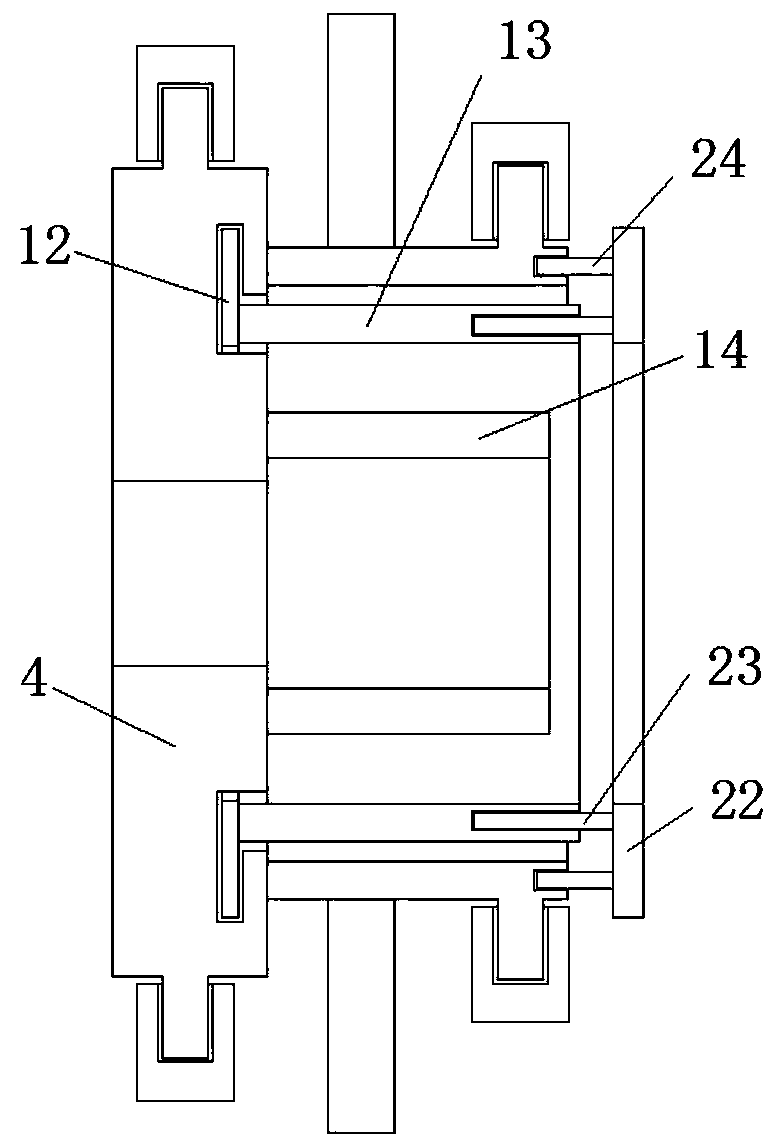
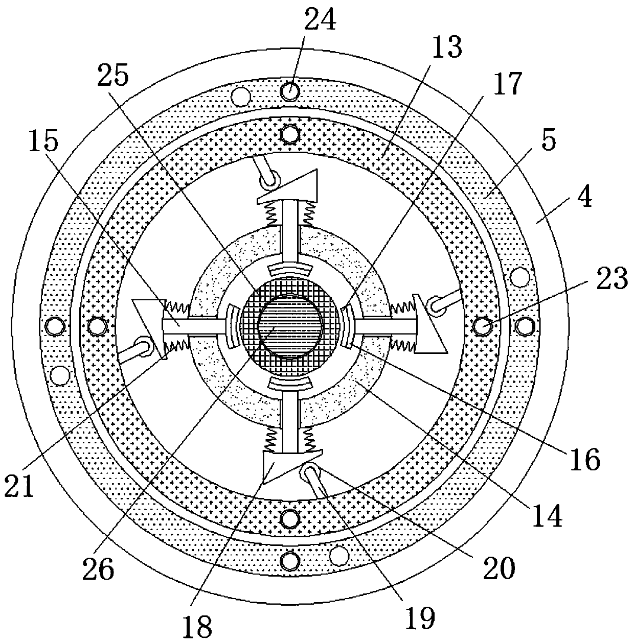
[0028] Such as Figure 1-4 As shown, this embodiment is basically the same as Embodiment 1. Preferably, the fixing mechanism includes a control ring 22, the control ring 22 is vertically arranged on the side of the outer cylinder 5 away from the vertical ring 4, and one side of the control ring 22 is fixed A long plunger 23 and a short plunger 24 are welded, and the side of the rotating inner cylinder 13 away from the vertical ring 4 is provided with a deep slot, one end of the long plunger 23 is stuck in the deep slot, and the outer cylinder 5 is far away from the vertical ring 4. One side of the straight ring 4 is provided with a shallow card slot, and one end of the short insertion rod 24 is clamped in the shallow card slot.

[0029] In this embodiment, the control ring 22 can control the relative position of the outer cylinder 5 and the rotating inner cylinder 13, and then control the relative position between the inclined contact plate 18 and the contact roller 20, thereb...

Embodiment 3

[0031] Such as Figure 1-4 As shown, this embodiment is basically the same as Embodiment 2. Preferably, there are several long insertion rods 23 and short insertion rods 24 respectively, and they are arranged on the same side of the control ring 22 in a circular equidistant manner, and there are several shallow card slots , and in groups of two by two, each group is set at a circular equidistant distance.


PUM


Abstract

The invention discloses an auxiliary screwing-up device for automobile part production. The device comprises a device base, a horizontal sliding groove is formed in the device base, two sliding platesarranged side by side are slidably connected to the inside of the horizontal sliding groove, and two rotating brackets are fixedly arranged on the top sides of the sliding plates; the top sides of the rotating brackets both extend to the vertical upper side of the device base, a vertical round ring and an outer cylinder are respectively erected on the top sides of the rotating brackets, and one end of the outer cylinder is fixedly welded to one side of the vertical round ring coaxially; a transmission gear ring fixedly sleeves the outer side of the outer cylinder body, a rotating seat is fixedly arranged on the top side of the device base, and a transmission gear column is rotatably connected to the inside of the rotating seat and is meshed with the transmission gear ring, and one end ofthe transmission gear ring is coaxially connected with a driven bevel gear fixedly. According to the device, a threaded cylinder and a threaded column can be quickly assembled, the manpower is saved,the production efficiency is improved, and the using requirements of people in production and living are met.

Description

technical field [0001] The invention relates to the technical field of automobile assembly, in particular to an auxiliary tightening device for the production of automobile parts. Background technique [0002] Now in the process of automobile production, the combination of long rod threaded sleeve and threaded rod is often used to connect the connecting rods. This connection method has better stability and is more convenient in the process of length adjustment. , in order to have a larger distance adjustment and a more stable state, people will use a longer threaded rod and a deeper threaded sleeve, which makes it extremely time-consuming to connect the threaded sleeve and threaded rod, and this The first process is completed manually by people, which is extremely labor-intensive, and the efficiency is extremely low, which cannot meet the needs of people in production and life. Contents of the invention [0003] The purpose of the present invention is to solve the problem...

Claims


Application Information

Patent Timeline
Patent Type & Authority Patents(China)
IPC IPC(8): B23P19/06
CPCB23P19/06
Inventor 査凌宇
Owner ANQING JIAN AUTO PART FORGING & ROLLING
Features
  • R&D
  • Intellectual Property
  • Life Sciences
  • Materials
  • Tech Scout
  • Unparalleled Data Quality
  • Higher Quality Content
  • 60% Fewer Hallucinations
Learn More