Food cutter
A cutter and food technology, applied in metal processing, household utensils, applications, etc., can solve the problems of cumbersome operation, high production cost, complex structure, etc., and achieve the effect of simple and convenient operation, high cutting efficiency, simple structure and
- Summary
- Abstract
- Description
- Claims
- Application Information
AI Technical Summary
Problems solved by technology
Method used
Image

Examples
Embodiment Construction
[0027] The present invention will be described in further detail below by means of specific embodiments:
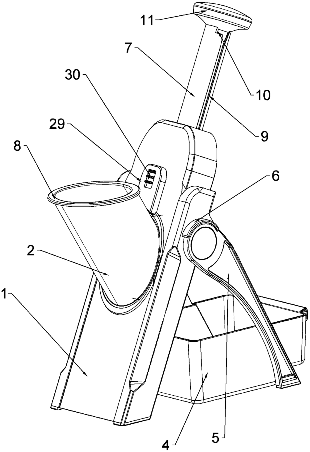
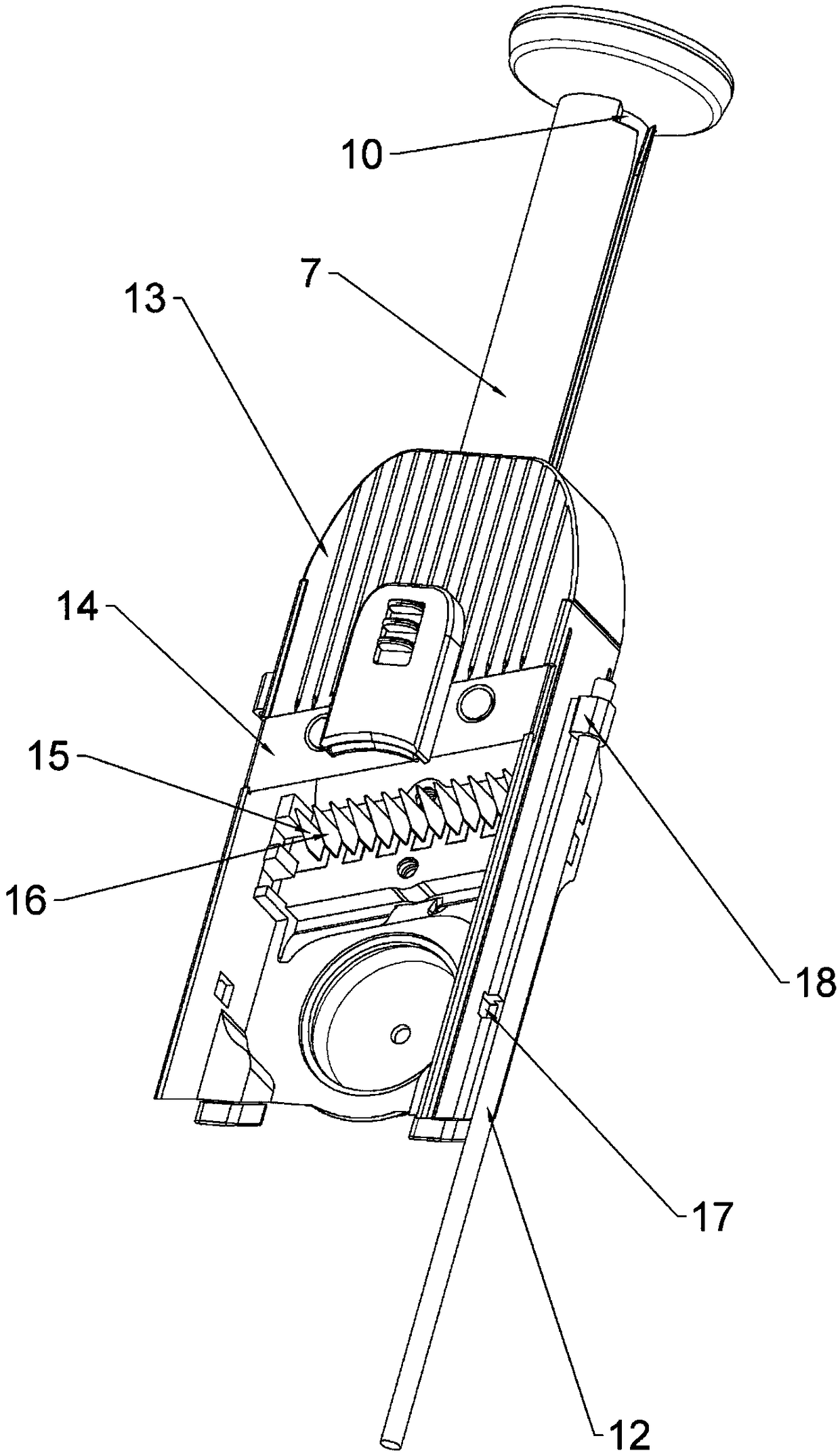
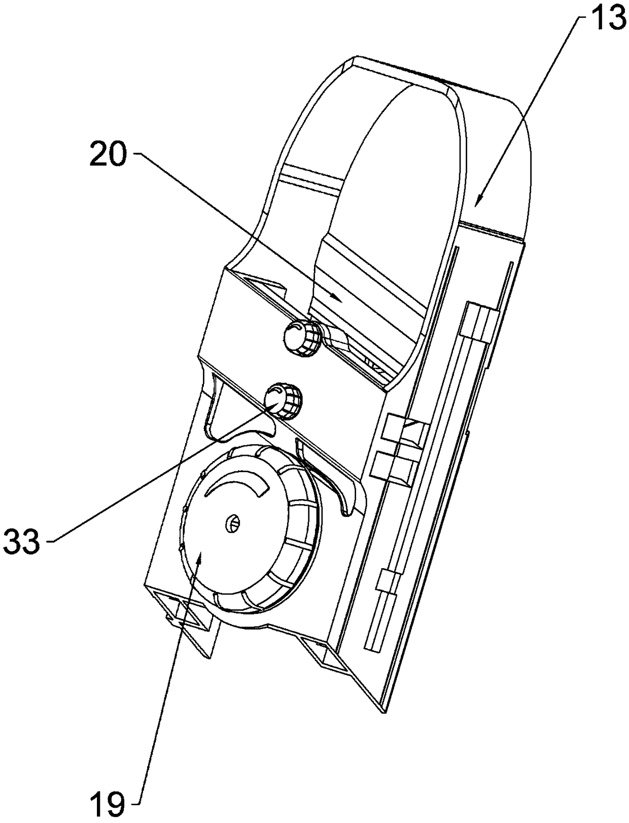
[0028] The reference signs in the accompanying drawings of the description include: housing 1, discharge barrel 2, collection frame 4, bracket 5, limit plate 6, push-pull rod 7, pressing member 8, slide groove 9, limit groove 10, handshake 11. Slide rail 12, sliding member 13, first cutter 14, first cutter 15, second cutter 16, chute 17, protrusion 18, bolt 19, slider 20, feed port 21, raised bar 22. The first through hole 23, the flange 24, the notch 25, the connecting rod 26, the pressing plate 27, the mesh 28, the casing 29, the toggle piece 30, the slideway 31, the channel 32, the threaded rod 33, the first Knife seat 34, threaded through hole 35, second knife seat 36.
[0029] The embodiment is basically as Figure 1-Figure 3 As shown: a food cutter, including a housing 1, a first pressure spring and a discharge cylinder 2, this solution also includes a cutting mec...
PUM
 Abstract
Description
Claims
Application Information
PatSnap Eureka turns technology decisions into work you can execute. Powered by our Innovation Knowledge Graph, it runs expert workflows across engineering, life sciences, materials and intellectual property. Get your review-ready output in minutes.


