

Electric servo brake device with various working modes
A technology of electric servo and braking device, applied in the direction of braking transmission, brake, transportation and packaging, can solve the problems of system optimization, cost reduction, high use and processing cost, and achieve the effect of improving the scope of application and improving reliability
- Summary
- Abstract
- Description
- Claims
- Application Information
AI Technical Summary
Problems solved by technology
Method used
Image

Examples
Embodiment 1
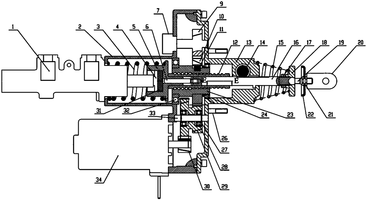
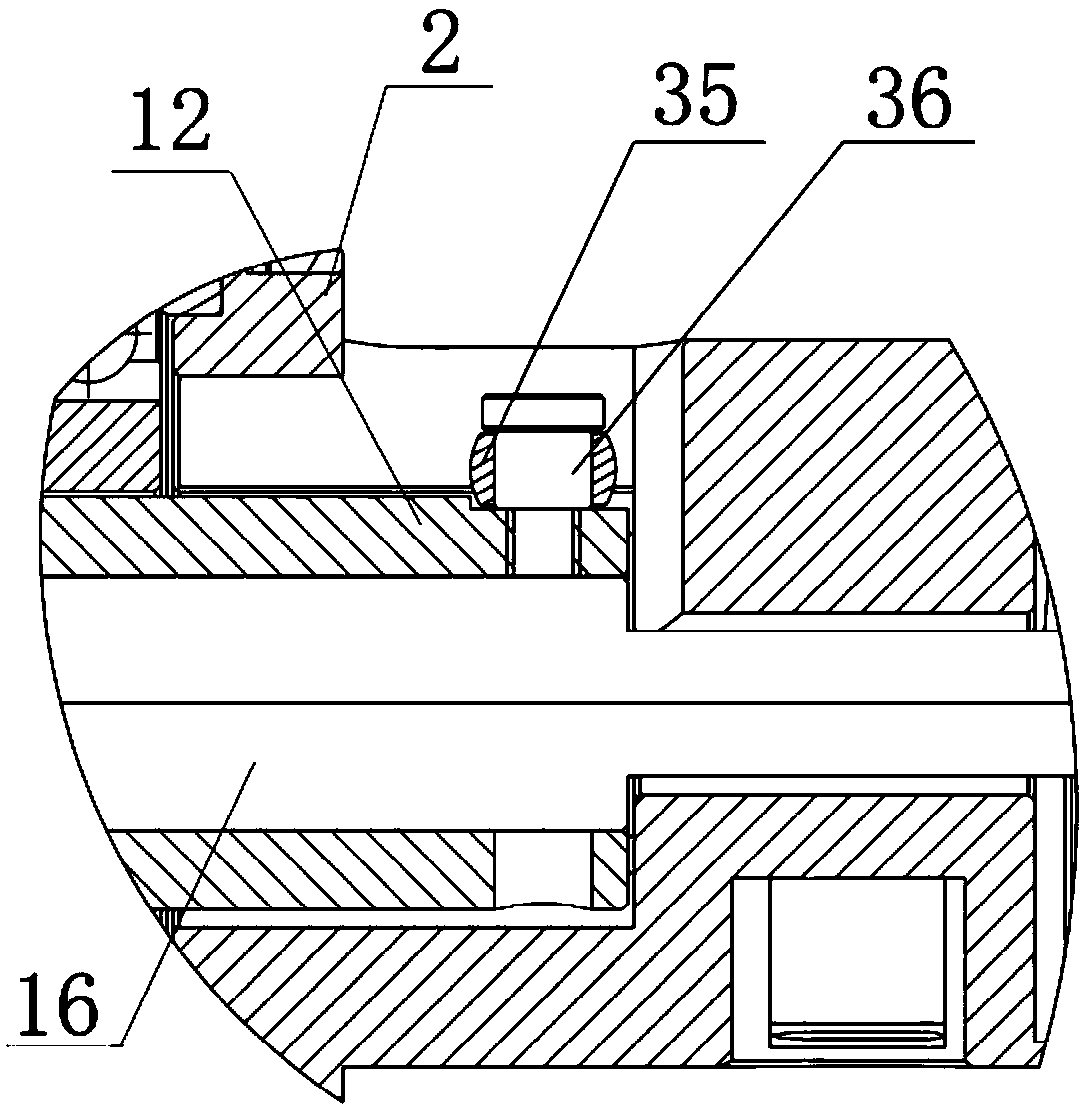
[0040] Such as Figure 1-Figure 2As shown, the electric servo braking device with multiple working modes of the present invention includes a housing 2, an end cover 13, a brake master cylinder 1, a ball screw 12, a transmission mechanism, a pushing mechanism and a pedal mechanism, and the housing 2 It is connected with the end cover 13, and a cavity is formed between the housing 2 and the end cover 13, and a ball screw 12 is installed in the center of the cavity, and the transmission mechanism is connected with the ball screw 12 for output torque driving The master cylinder 1 is activated to achieve servo braking. The piston of the brake master cylinder 1 is installed in the housing 2. The piston is pushed in its braking direction by a push mechanism connected with the pedal mechanism. The push mechanism is used to transmit The driving force of the pedal mechanism; the ball screw 12 includes a screw nut 23, a first bearing 32 and a second bearing 24, and the screw nut 23 passe...
Embodiment 2
[0047] Using the electric servo brake device of the present invention in the brake-by-wire mode:
[0048] In the brake-by-wire mode, the gap between the inner annular end surface of the tray 5 and the front end surface of the auxiliary push rod 6 is S0, the pedal force will not be transmitted to the reaction disc 31, and all the pedal force is provided by the conical spring 15.
[0049] In the wire control mode, when the driver depresses the pedal, the pedal force of the pedal is transmitted to the conical spring 15 via the U-shaped hinge 20, and then the pedal is transmitted to the auxiliary push rod 6 under the action of the push rod 16; The required target braking force is produced by the regenerative braking of the power motor of the automobile, and its target braking force depends on the stroke of the pedal (the pedal stroke is measured by the second sensor gear 14 and the second angle sensor).
[0050] When the power battery of the car allows charging or the regenerative...
Embodiment 3
[0053] Using the electric servo braking device of the present invention in the power-assisted braking mode,
[0054] Control the alignment of the inner annular end face of the tray 5 with the front end face of the auxiliary push rod 6 to eliminate the gap S0 between the inner annular end face of the tray 5 and the front end face of the auxiliary push rod 6 and ensure that the reaction disc 31 reacts on the ball screw 12 and the force of the push rod become a fixed ratio. The first rotation angle sensor (non-contact rotation angle sensor) connected to the first sensor gear 9 is the lead screw stroke sensor, which is used to measure the stroke of the ball screw 12 . When the displacement difference between the control push rod 16 and the ball screw 12 is 0, the regenerative braking exits, and the braking force is all provided by the friction brake.
[0055] Among them, the braking deceleration is greater than 0.25g.
[0056] The reaction disc 31 is made of rubber material.
PUM
 Abstract
Description
Claims
Application Information