
Metal plate coil bundling device and bundling method

A technology for metal discs and equipment, applied in the directions of bundling materials, parts of bundling machinery, packaging, etc., can solve the problems of increasing labor intensity of workers, low production efficiency, high size, etc., and achieve improved bundling efficiency, compact structure, and automation. high degree of effect

Active Publication Date: 2018-11-23
成都金中机械设备制造有限公司
View PDF12 Cites 3 Cited by
  • Summary
  • Abstract
  • Description
  • Claims
  • Application Information

AI Technical Summary

Problems solved by technology

However, the outer diameter of the aluminum rod coil is Φ2250, the inner hole is Φ800, and the height is 1350. Due to its large size and weight of 2.5 to 2.8 tons, manual binding is very laborious, which not only reduces production efficiency, but also increases the labor intensity of workers.

Method used


Image

  • Metal plate coil bundling device and bundling method
  • Metal plate coil bundling device and bundling method
  • Metal plate coil bundling device and bundling method

Examples


Embodiment 1

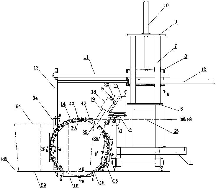
[0048] Embodiment one: if Figure 1~15 As shown, a metal coil binding equipment includes a binding trolley 1, a threading channel, a wire rod cutting mechanism 2 arranged on the binding trolley 1, a traction mechanism 3, a horizontal hydraulic slide 4, an oblique hydraulic slide 5, Vertical movement mechanism and horizontal movement mechanism, the traction mechanism 3 is installed on the traction wheel and the pressing wheel on the front surface of the platform B31, wherein the rotating shaft of the traction wheel is connected with the output shaft of the hydraulic motor, when the aluminum rod is placed on the traction wheel After it is between the pinch wheel and the hydraulic motor, the torque output by the hydraulic motor drives the traction wheel to rotate, thereby transporting the aluminum rod to the left.

[0049] Described vertical motion mechanism comprises the platform A6 that is fixed on the binding trolley 1, the vertical guide rail 7 that is fixed on the platform A...

Embodiment 2

[0070] Embodiment two: if Figure 16 As shown, a metal coil binding equipment, the difference between this embodiment and Embodiment 1 is that it includes a hinge seat 66, a main beam 67, a movable plate 13, a main oil cylinder 69 and an auxiliary oil cylinder 70, and the right end of the main beam 67 The bottom of the bottom is provided with a hinge seat 66, the hinge seat 66 is arranged on the platform A6, the lower surface of the left end of the main beam 67 is provided with an auxiliary oil cylinder 70, the auxiliary oil cylinder 70 is arranged parallel to the main beam 67, and the acting end of the piston rod of the auxiliary oil cylinder 70 A movable plate 13 is arranged on the movable plate 13, and a main channel 14 is arranged on the movable plate 13. The cylinder barrel of the main oil cylinder 69 is hinged on the strapping trolley 1, and the piston rod of the main oil cylinder 69 is hinged on the main beam 67. By controlling the extension of the piston rods of the ma...


PUM


Abstract

The invention discloses a metal plate coil bundling device. The metal plate coil bundling device comprises a bundling trolley (1), a threading channel, a wire rod cutting mechanism (2) arranged on thebundling trolley (1), a drawing mechanism (3), a horizontal hydraulic sliding table (4), an inclined hydraulic sliding table (5), a vertical moving mechanism and a horizontal moving mechanism. The invention further discloses a bundling method. The beneficial effect is that the metal plate coil bundling device is compact in structure, high in automation degree, and firm in bundling, and capable ofreducing labor intensity of a worker, and improving bundling efficiency.

Description

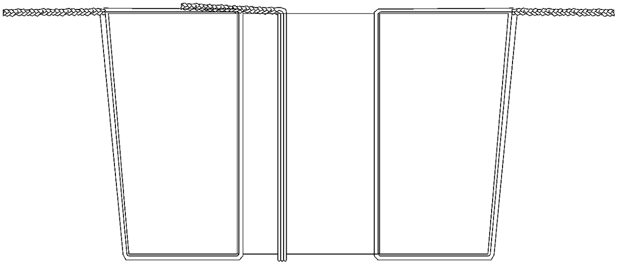
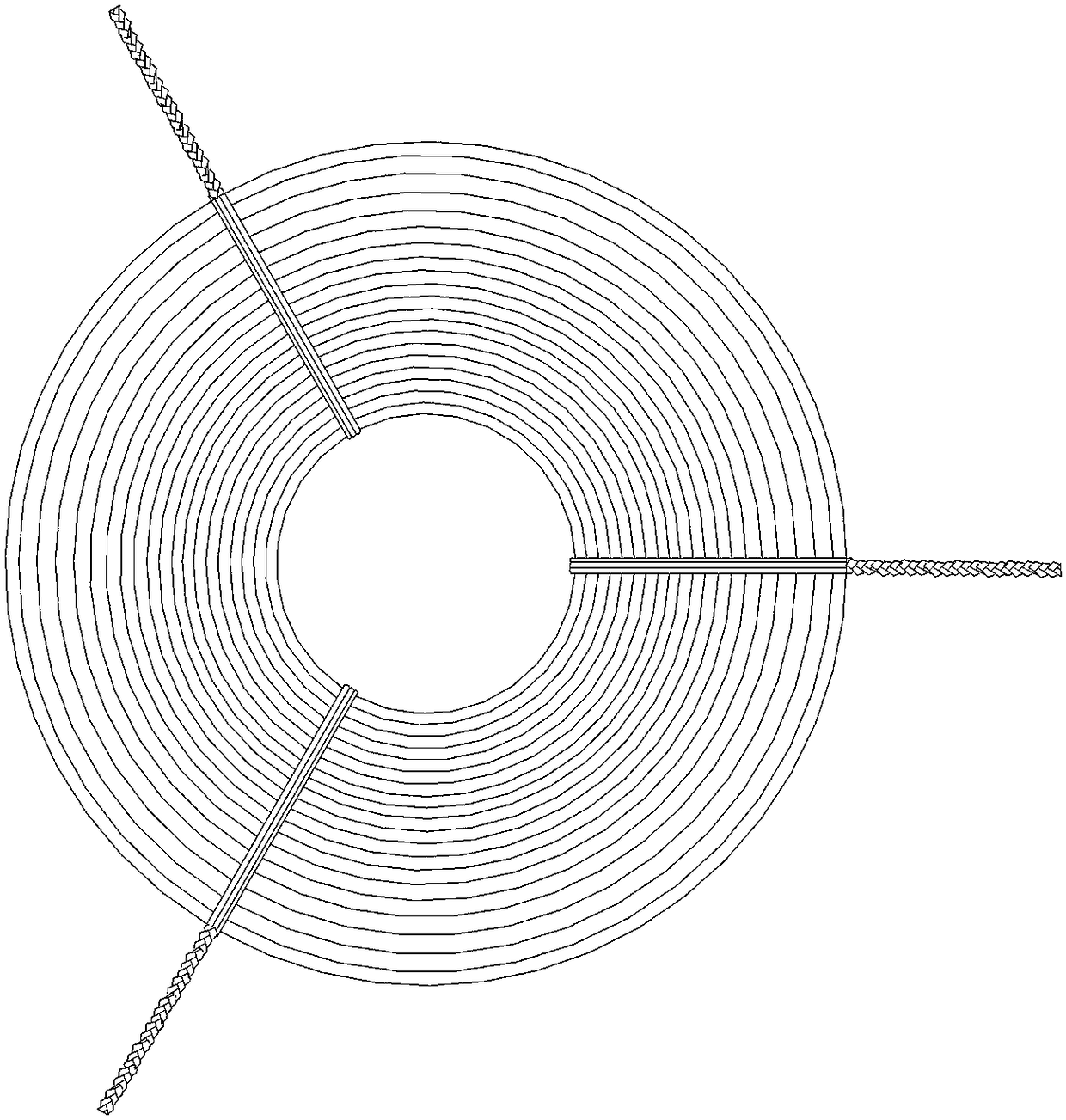
technical field [0001] The invention relates to the technical field of aluminum rod coil binding, in particular to a metal coil binding equipment and a binding method. Background technique [0002] At present, aluminum rods are produced through the continuous casting and rolling production line, and after passing through the last rolling mill, they are harvested into coils through the rod receiving equipment, and the aluminum rod coils are formed, such as Figure 1~2 A schematic view of the structure of an aluminum coil is shown. Since the aluminum rods in each circle are very evacuated after coiling, it is necessary to bundle 3 strands of wire rods in every 120° direction of the coiling circumference of each coil, and the wire rods used for bundling are the aluminum rods produced by ourselves. The existing binding process is as follows: workers first cut the wire pole into three sections, each section is about 16 meters long, and then fold it into 3 strands, and place them ...

Claims


Application Information

Patent Timeline
Patent Type & Authority Applications(China)
IPC IPC(8): B65B27/06B65B13/06B65B13/18B65B61/06
CPCB65B13/06B65B13/18B65B27/06B65B61/06Y02P70/10
Inventor 钟天富
Owner 成都金中机械设备制造有限公司
Learn More