Shaft sleeve continuous vertical lifting mechanism

A vertical lifting and bushing technology, which is applied to lifting devices, lifting frames, conveyor objects, etc., can solve the problems of narrow application range, falling bushing, clamping and fixing of bushings, etc., and achieves reasonable structural design, convenient adjustment, Smooth and smooth reciprocating swing effect

Inactive Publication Date: 2018-11-23
晋正正
View PDF0 Cites 18 Cited by
  • Summary
  • Abstract
  • Description
  • Claims
  • Application Information

AI Technical Summary

Problems solved by technology

During the processing and use of the shaft sleeve, it is necessary to smoothly and accurately lift the shaft sleeve and transfer it to the required processing station for deep processing and testing of subsequent processes such as grinding and distance measurement. The existing shaft sleeve is difficult to carry out horizontally and continuously The automatic centering of the shaft sleeve cannot be realized during the translation process, which makes it difficult to load the shaft sleeve horizontally and accurately. During the lifting process of the existing shaft sleeve, it is difficult to clamp and fix the shaft sleeve smoothly and firmly, resulting in The shaft sleeve is easy to fall off during the lifting process, resulting in production safety accidents, and the existing shaft sleeve lifting mechanism is difficult to clamp and fix shaft sleeves of various sizes and specifications, and the scope of application is narrow. After the height, it is difficult to transfer the shaft sleeve to the required processing station through horizontal and convenient rotation, resulting in the need for secondary transfer of the shaft sleeve during the lifting and transfer process. The efficiency of the shaft sleeve’s lifting and transfer is low, which cannot meet the needs of processing

Method used


Image

  • Shaft sleeve continuous vertical lifting mechanism
  • Shaft sleeve continuous vertical lifting mechanism
  • Shaft sleeve continuous vertical lifting mechanism

Examples


Embodiment Construction

[0016] In order to further describe the present invention, the specific implementation of a shaft sleeve continuous vertical lifting mechanism will be further described below in conjunction with the accompanying drawings. The following examples are explanations of the present invention and the present invention is not limited to the following examples.

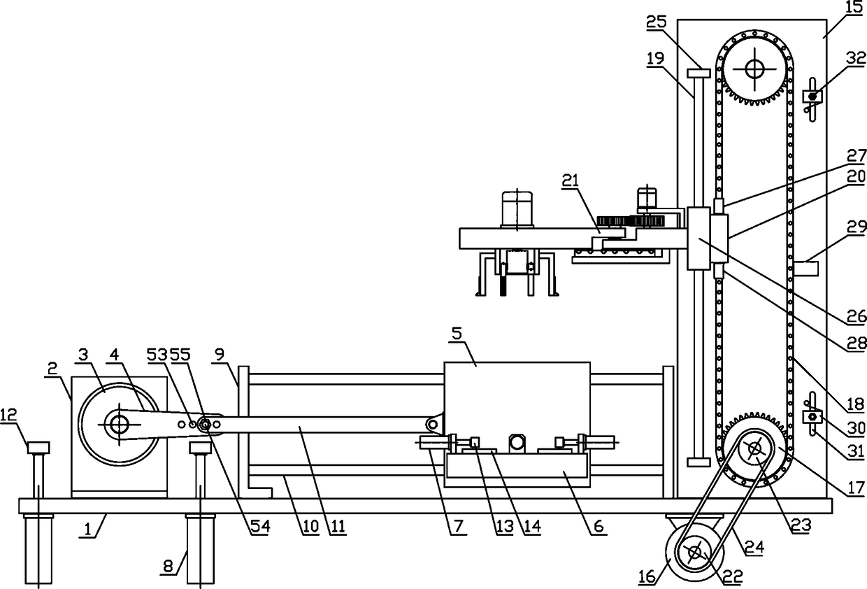
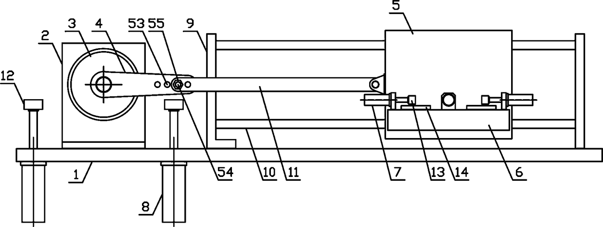
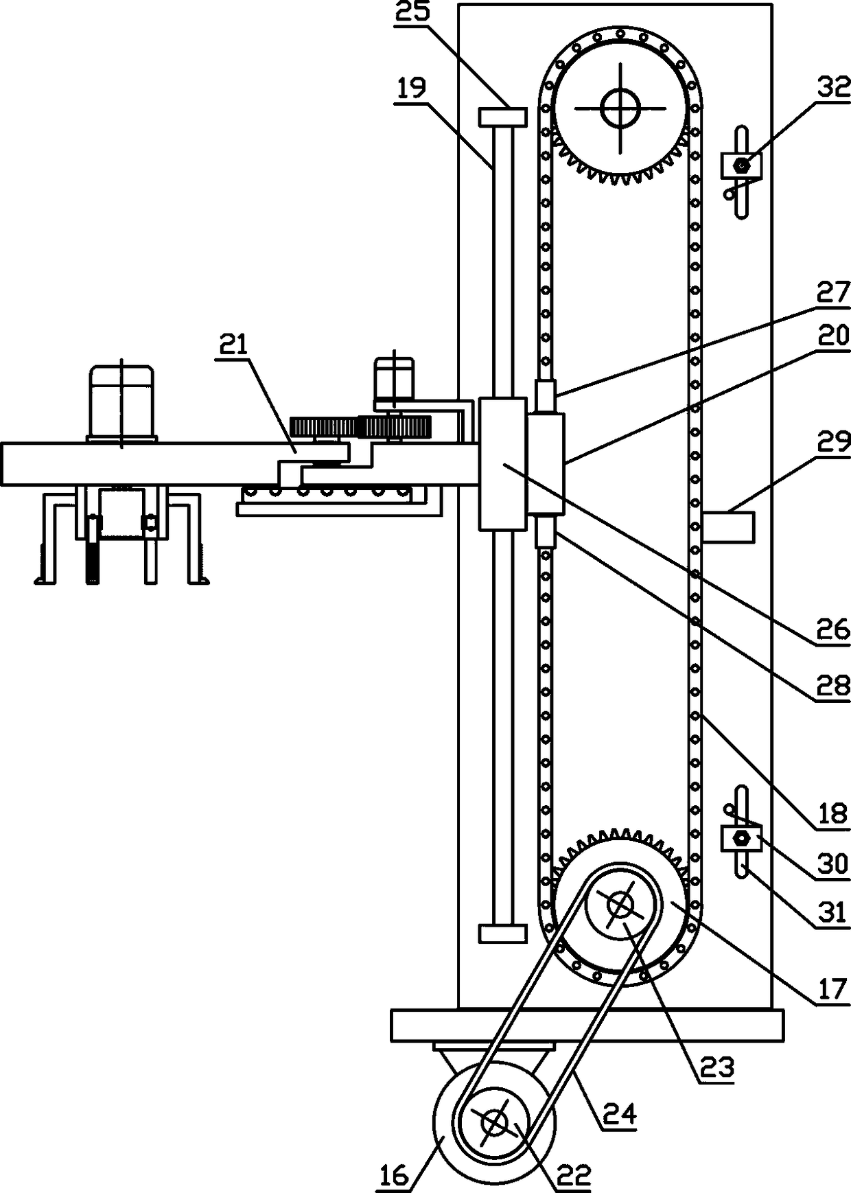
[0017] Such as figure 1 As shown, a shaft sleeve continuous vertical lifting mechanism of the present invention includes a fixed bracket 1, a material shifting mechanism and a lifting mechanism. side, such as figure 2 As shown, the material shifting mechanism of the present invention includes a connecting support 2, a swing cylinder 3, a rotating connecting plate 4, a translation support 5, a material receiving connecting plate 6, a correcting cylinder 7 and a buffer 8, and the connecting support 2 is vertically arranged on On the upper side of the fixed bracket 1, the swing cylinder 3 is fixed horizontally on the side of th...


PUM


Abstract

The invention discloses a shaft sleeve continuous vertical lifting mechanism, and belongs to the field of workpiece machining mechanical equipment. The shaft sleeve continuous vertical lifting mechanism comprises a fixing bracket, a shaft sleeve transferring mechanism and a lifting mechanism. Buffers are fixedly arranged on the fixing bracket on both ends of one side of a swinging cylinder separately, and the buffers are arranged vertically upwards. A shaft sleeve receiving connection plate is horizontally and fixedly arranged on one side of a translation bracket, rotating sprockets are connected to the upper and lower sides of a lifting bracket, and the upper and lower sides of a lifting chain separately mesh with the rotating sprockets in a winding mode. A lifting guide plate is slidablyarranged on a lifting guide rod in the vertical direction, limiting switches are separately arranged on the lifting bracket on the upper and lower sides of a limiting connecting plate, and a shaft sleeve clamping mechanism is horizontally arranged on one side of the lifting guide plate. The shaft sleeve continuous vertical lifting mechanism is reasonable in structural design, can clamp and fix shaft sleeves of various sizes and specifications conveniently and firmly, and can vertically lift the shaft sleeves more stably and efficiently so that the shaft sleeves can be transferred to requiredworking positions, the automation degree of shaft sleeve transferring is improved, and the needs of processing and use are met.

Description

technical field [0001] The invention belongs to the field of workpiece processing machinery and equipment, in particular to a continuous vertical lifting mechanism for shaft sleeves, which is mainly used in the field of continuous transfer processing of shaft sleeves. Background technique [0002] The structural shape of the axle sleeve is a cylindrical structure. There are many types of axle sleeves, which are classified according to the use of the axle sleeves, mainly including axle sleeves, connecting sleeves and transmission sleeves, etc. Among them, the axle sleeves are mainly used in automobiles. The semi-axle sleeve is an important part of the automobile drive axle assembly. It is integrated with the drive axle housing to fix the axial relative position of the left and right drive wheels, and supports the frame and all parts on it together. The quality of the assembly, and at the same time bear the road surface reaction force and moment transmitted from the wheels whe...

Claims


Application Information

Patent Timeline
Patent Type & Authority Applications(China)
IPC IPC(8): B65G47/90B66F7/02B66F7/28
CPCB65G47/901B66F7/02B66F7/28
Inventor 晋正正
Owner 晋正正
Why Eureka
Try Eureka