Profile structure of elevator car ceiling lamp and elevator car ceiling lamp

A technology for elevator cars and profiles, which is applied to elevators, transportation and packaging in buildings. It can solve the problems of customers feeling uncomfortable, increasing the height of the ceiling, increasing the number of lamps, etc., and achieves simple process, improved comfort, and reduced The effect of the dark zone phenomenon

Pending Publication Date: 2018-11-23
杭州多依辰科技有限公司
View PDF0 Cites 2 Cited by
  • Summary
  • Abstract
  • Description
  • Claims
  • Application Information

AI Technical Summary

Problems solved by technology

It has the following disadvantages: the traditional ceiling lamp is installed on the side of the ceiling, because the height of the lamp itself and the linear distance from the light-emitting surface to the acrylic board are limited, if the light-emitting surface is too small, the dark area displayed on the acrylic surface can be seen, Customers feel uncomfortable; due to the use of line light sources, the light will be uneven after being emitted. In order to achieve a good effect, the height of the ceiling and the number of lamps can only be further increased, which is not economical

Method used


Image

  • Profile structure of elevator car ceiling lamp and elevator car ceiling lamp
  • Profile structure of elevator car ceiling lamp and elevator car ceiling lamp
  • Profile structure of elevator car ceiling lamp and elevator car ceiling lamp

Examples


Embodiment

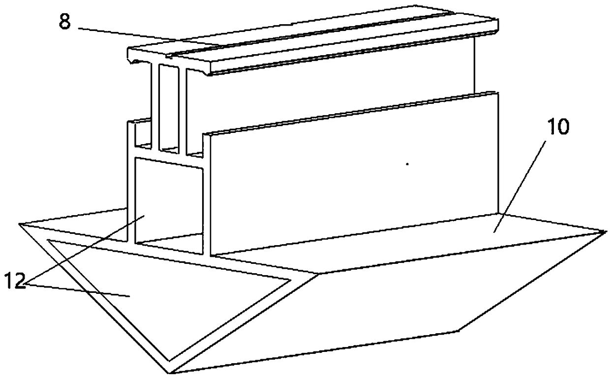
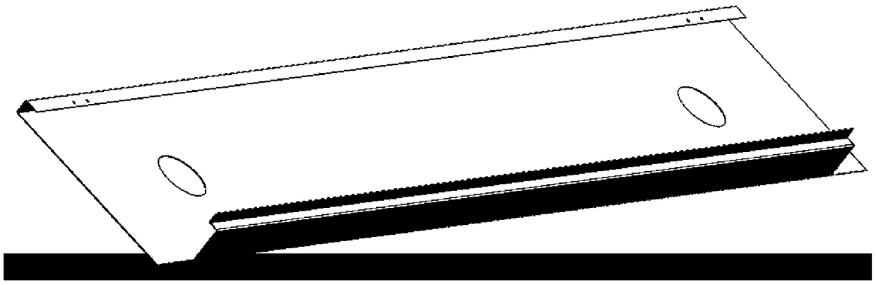
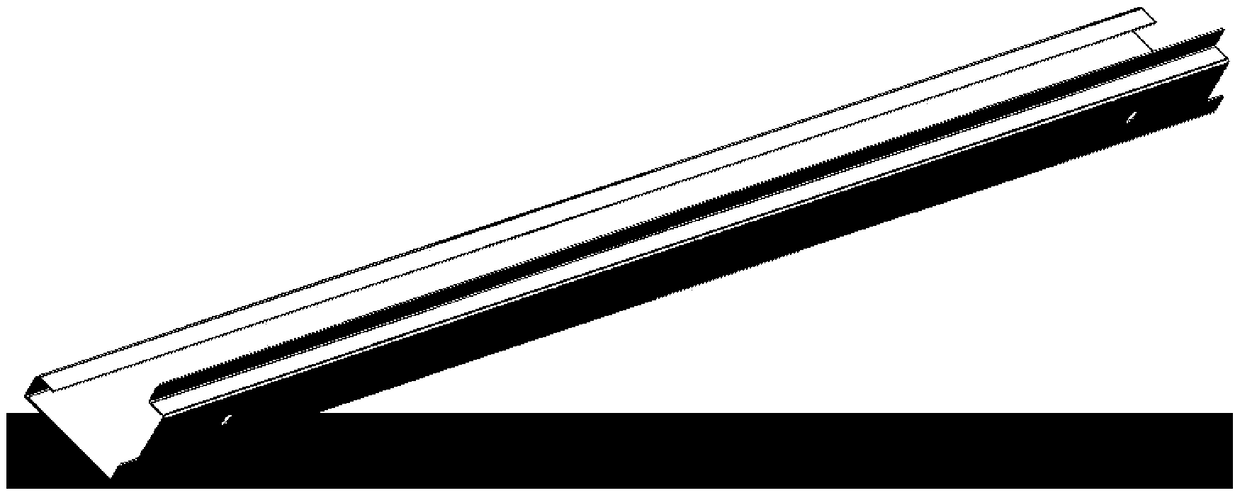
[0026] Embodiment: As shown in the accompanying drawings, this elevator car dome light profile structure mainly includes a lamp fixing card 7, a punching positioning groove 8, a reinforcement hole 9, a lamp mounting surface 10, an assembly positioning groove 11, and a mounting rod through groove 12 , profile A13, profile B14, a reinforcing hole 9 is set in the middle of the profile A13, a lamp fixing card 7 is above the reinforcing hole 9, a lamp mounting surface 10 is set outside the lower part of the reinforcing hole 9, and multiple punching holes are provided on both sides and the upper side of the profile A13 for positioning Slot 8, assembly positioning groove 11 is set on the inner side of the bottom of the profile A13, the lamp fixing card 7 is on both sides of the upper end of the profile B14, the lower part of the lamp fixing card 7 is connected to the installation rod through groove 12, and the upper surface on both sides of the installation rod through groove 12 is the...


PUM


Abstract

The invention discloses a profile structure of an elevator car ceiling lamp and an elevator car ceiling lamp. The profile structure of the elevator car ceiling lamp mainly comprises a front border andthe like. The front border, a rear border, a left border and a right border are connected to form a rectangular frame. A middle cross beam is connected between the left border and the right border, and a middle vertical beam is connected between the front border and the rear border. The front border, the rear border, the left border and the right border are made from profiles A. Reinforcing holesare formed in the profiles A. Lamp fixing clamps are arranged above the reinforcing holes. Lamp installation faces are arranged on the outer sides of the lower portions of the reinforcing holes. A plurality of punching positioning grooves are formed in the two side and the upper side of each profile A. An assembling positioning groove is formed in the inner side of the bottom of each profile A. The middle cross beam and the middle vertical beam are made from profiles B. Lamp fixing clamps are arranged on the two sides of the upper end of each profile B, and an installation rod through grooveis connected to the lower portion of each profile B. The upper surfaces of the two sides of each installation rod through groove are lamp installation faces. Punching positioning grooves are formed inthe top ends of the profiles B. According to the profile structure of the elevator car ceiling lamp and the elevator car ceiling lamp, the profile structure is formed by assembling aluminum profiles,the ceiling height is decreased to 60 mm, an area source is adopted, and thus, light is evenly emitted from the ceiling; the dimming technique is adopted so that the strength, color temperature and hue of the elevator car ceiling lamp can be changed; and the lateral light-emitting technique is adopted, so that dark areas are reduced.

Description

technical field [0001] The invention relates to the field of elevator dome lights, in particular to an elevator car dome light profile structure and an elevator car dome light. Background technique [0002] The traditional elevator car ceiling is generally formed by cutting, punching, folding and welding processes with 1.2mm steel plates, and uses four to six installation connectors to connect with the elevator car. The length of the installation connectors is the same as the bending part The sum of the heights is usually above 170mm, and some are even higher. Since the bending parts of the ceiling frame are limited by the bending machine and tools, the size of the bending part in the bending direction has certain requirements. In order to improve the manufacturability, the traditional ceiling frame usually has a net height of more than 170mm; the traditional ceiling light frame The production process is complicated. First, the steel plate must be cut according to the size ...

Claims


Application Information

Patent Timeline
Patent Type & Authority Applications(China)
IPC IPC(8): B66B11/02
CPCB66B11/0233
Inventor 陈小元王凯平袁玲
Owner 杭州多依辰科技有限公司
Why Eureka
Try Eureka