Eureka AIR delivers breakthrough ideas for toughest innovation challenges, trusted by R&D personnel around the world.

High-temperature pellet cooling method and device thereof

A technology of a cooling device and a cooling method, which is applied in the heat exchange field of waste heat boilers or heat exchangers, can solve the problems of unstable air temperature, large resistance and instability of cooling air penetrating through the material layer, etc.

Pending Publication Date: 2018-11-23
JIANGSU DONGJIU HEAVY IND
View PDF0 Cites 0 Cited by
  • Summary
  • Abstract
  • Description
  • Claims
  • Application Information

AI Technical Summary

Problems solved by technology

[0002] In the actual production of pellets, a ring cooler is conventionally used to directly penetrate the pellet material layer to cool the high-temperature pellets. In order to provide a large amount of hot air to adapt to strong wind drying, it is necessary to set up a hot air generator to heat the insufficient air. , sent to the low-temperature drying section, generally 1-3 sections of 1000°C-350°C hot air are introduced into the previous process for use, and the 4th section of 100°C exhaust gas is discharged through the chimney of the ring cooler, which will inevitably cause energy waste and be affected by the existing ring cooling Due to the limitation of mechanical sealing technology, the air leakage coefficient of the existing annular coolers is more than 10%, resulting in an increase in the air volume of the fan, resulting in an increase in fan power, and the operation between the trolley and the fan hood of the annular cooler is controlled at a slight positive pressure, and the dusty gas Air leakage deteriorates the working environment around the annular cooler, leading to an increase in environmental protection costs; because the material layer of the annular cooler is more than 70mm and the material layer is unevenly distributed, the resistance of the cooling air to penetrate the material layer is large, resulting in high fan operating power and Unstable, the ring cooler is unstable during operation, making the air temperature in each section unstable, which is not conducive to the full circulation of the air in each section

Method used


Image

  • High-temperature pellet cooling method and device thereof
  • High-temperature pellet cooling method and device thereof

Examples


Embodiment Construction

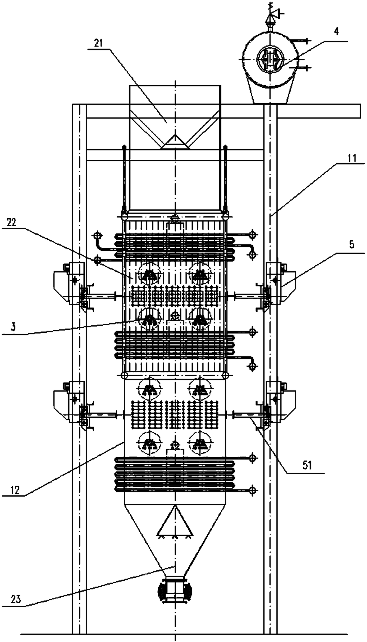
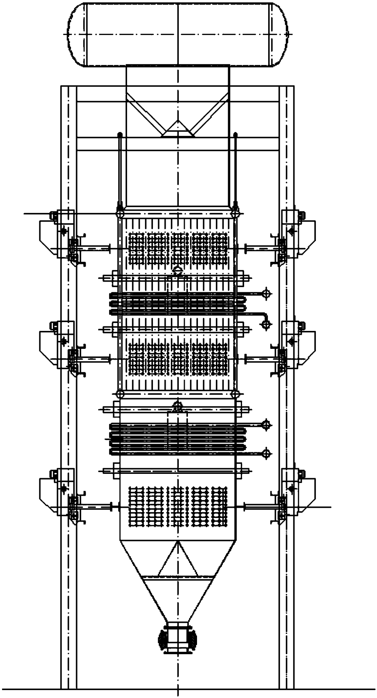
[0023] The following will clearly and completely describe the technical solutions in the embodiments of the present invention with reference to the accompanying drawings in the embodiments of the present invention. Obviously, the described embodiments are only some, not all, embodiments of the present invention. The following description of at least one exemplary embodiment is merely illustrative in nature and in no way taken as limiting the invention, its application or uses. Based on the embodiments of the present invention, all other embodiments obtained by persons of ordinary skill in the art without creative efforts fall within the protection scope of the present invention. The relative arrangements, expressions and numerical values ​​of components and steps set forth in these embodiments do not limit the scope of the present invention unless specifically stated otherwise. At the same time, it should be understood that, for the convenience of description, the sizes of the...


PUM

PropertyMeasurementUnit
diameteraaaaaaaaaa

Abstract

The invention discloses a high-temperature pellet cooling method and a device thereof. The method comprises the following steps: pellets to be cooled fall under the effect of self gravity after entering a closed cavity from a feed port formed in the upper end of the closed cavity; in the falling process, the pellets exchange heat with a cooling medium-air in each heat exchange tube bundle transversely arranged in the closed cavity from top to bottom, so that the pellets to be cooled are cooled below 150 DEG C; finally, the pellets are discharged from a discharge port formed in the lower end ofthe closed cavity; and the cooling medium-air output from high-temperature sides of all the heat exchange tube bundles is introduced into a pellet production kiln after collection through pipes for pellet production. The method has no air leakage loss, uses all heat, is reliable in pressure, and reduces the power of cooling air.

Description

technical field [0001] The invention relates to a high-temperature pellet cooling method and a device thereof, and mainly relates to the technical field of waste heat boiler or heat exchanger heat exchange. Background technique [0002] In the actual production of pellets, a ring cooler is conventionally used to directly penetrate the pellet material layer to cool the high-temperature pellets. In order to provide a large amount of hot air to adapt to strong wind drying, it is necessary to set up a hot air generator to heat the insufficient air. , sent to the low-temperature drying section, generally 1-3 sections of 1000°C-350°C hot air are introduced into the previous process for use, and the 4th section of 100°C exhaust gas is discharged through the chimney of the ring cooler, which will inevitably cause energy waste and be affected by the existing ring cooling Due to the limitation of mechanical sealing technology, the air leakage coefficient of the existing annular cooler...

Claims


Application Information

Patent Timeline
Patent Type & Authority Applications(China)
IPC IPC(8): C22B1/26
CPCC22B1/26
Inventor 杨成陈长景
Owner JIANGSU DONGJIU HEAVY IND
Why Eureka
Eureka Blog
Learn More