Clutch structure for electric hammers

A technology of electric hammer and clutch, which is applied in the direction of mutually meshing clutches, clutches, mechanical drive clutches, etc., and can solve the problems of moving up the meshing point of the cylindrical gear, lengthening the gear shaft of the motor, and failing to keep the meshing point of the gears on the same level.

Pending Publication Date: 2018-11-23
HUALI ELECTRICAL APPLIANCE MFG CO LTD
View PDF0 Cites 0 Cited by
  • Summary
  • Abstract
  • Description
  • Claims
  • Application Information

AI Technical Summary

Problems solved by technology

However, when the bearing at the lower end of the small bevel gear assembly adopts a needle bearing, the meshing point of the cylindrical gear will be moved up. If the clutch structure of the chisel gear still adopts the traditional layout of the clutch on the upper gear and the lower gear, it

Method used


Image

  • Clutch structure for electric hammers
  • Clutch structure for electric hammers
  • Clutch structure for electric hammers

Examples


Embodiment Construction

[0026] In order to make the object, technical solution and advantages of the present invention clearer, the present invention will be further described in detail below in conjunction with the accompanying drawings and embodiments. It should be understood that the specific embodiments described here are only used to explain the present invention, not to limit the present invention.

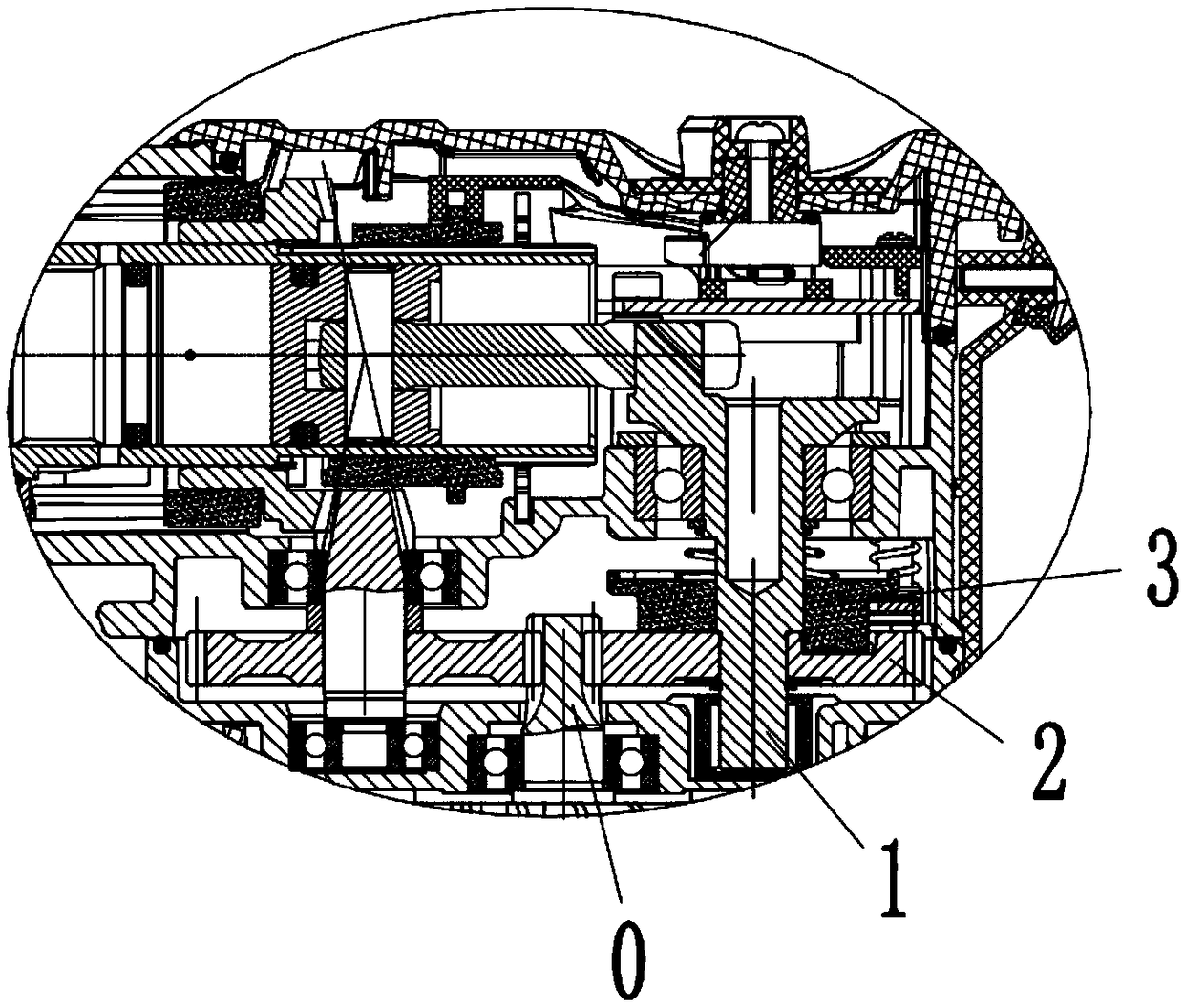
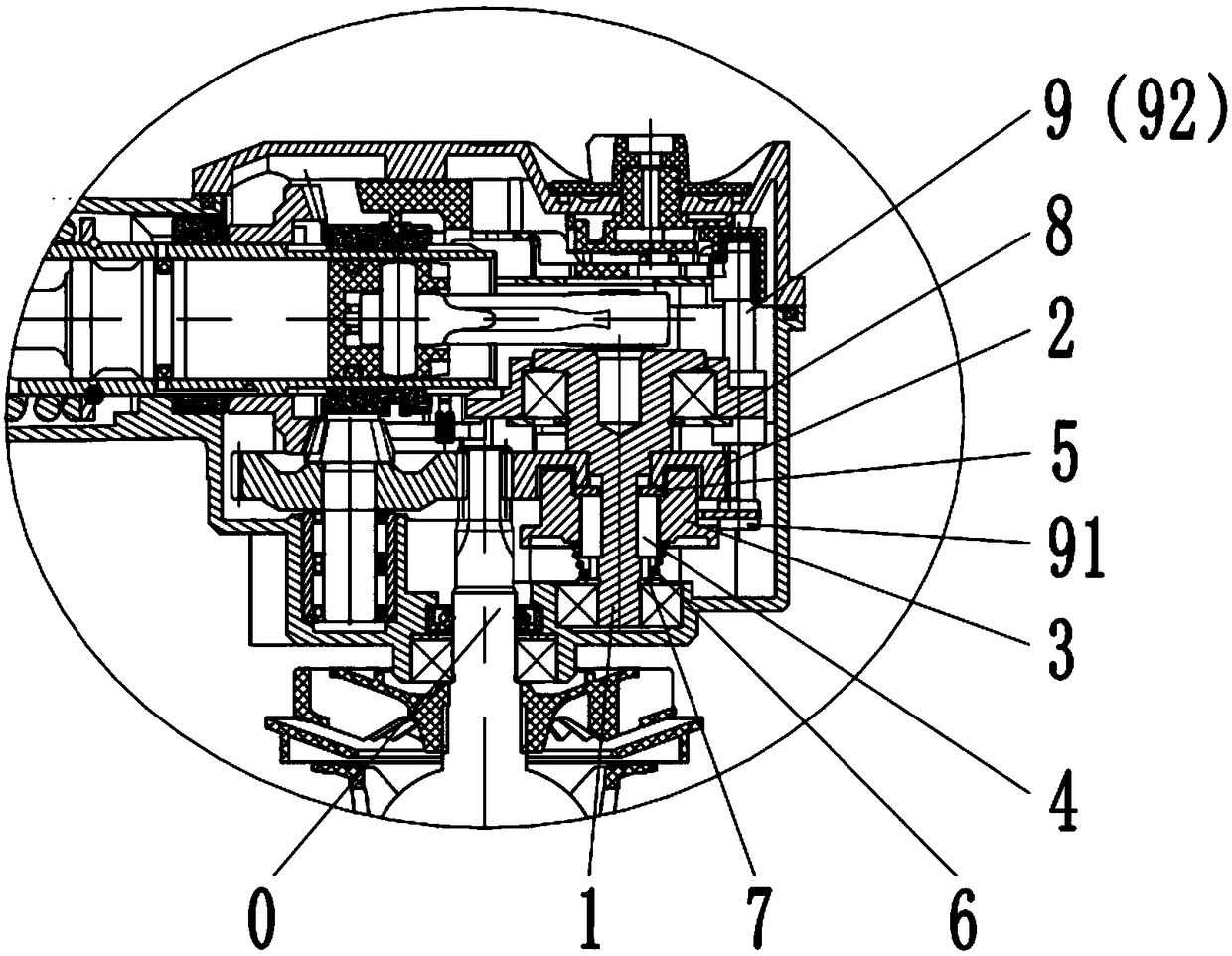
[0027] like figure 1 The clutch structure of the shown existing electric hammer all adopts the layout that the clutch 3 is on the top and the clutch gear 2 is on the bottom. And as figure 2 As shown, when the bearing at the lower end of the bevel pinion gear assembly adopts a needle bearing, the meshing point of the clutch gear 2 will be moved upward. If the clutch structure of the chisel position still adopts the traditional layout of the clutch 3 on the upper clutch gear 2 In this way, the meshing point of the gears will move down, resulting in the elongation of the motor pinion shaft 0, which...


PUM


Abstract

The invention relates to a clutch structure for electric hammers. The clutch structure comprises a crankshaft, a clutch gear, a clutch, guide keys and a support gasket. Key grooves are formed in the crankshaft, the guide keys are fixedly mounted in the key grooves, the clutch gear sleeves the crankshaft, one end of the clutch gear is butted to a shaft shoulder of the crankshaft, the support gasketis mounted between the other end of the clutch gear and the guide keys, two sides of the support gasket cling to the clutch gear and the guide keys, the clutch sleeves the guide keys and can slide along the guide keys, a meshing structure is arranged between the clutch and the clutch gear, and the clutch is connected with the clutch gear when sliding toward the clutch gear, and is separated fromthe clutch gear when sliding towards the other side. The clutch structure for the electric hammers has the advantages that chiseling functional clutch can be carried out by the clutch structure, the clutch structure is compact, the overall volumes of the electric hammers can be diminished, and stress conditions of serrated shafts of motors can be improved.

Description

technical field [0001] The invention relates to the technical field of electric hammers, in particular to a clutch structure of electric hammers. Background technique [0002] The electric hammer is a commonly used electric tool. With the development of the electric tool industry, the requirements for its functions are getting higher and higher. [0003] The principle of the electric hammer is that while the transmission mechanism drives the drill bit to rotate, it also has a reciprocating hammering movement in a direction perpendicular to the rotary head. The electric hammer is driven by the transmission mechanism to drive the piston to reciprocate and compress the air in a cylinder. The periodic change of the air pressure in the cylinder drives the hammer in the cylinder to reciprocate and hit the top of the brick, as if we use a hammer to hit the brick, hence the name electric hammer. The electric hammer is popular among users because of its four functions of single hamm...

Claims


Application Information

Patent Timeline
IPC IPC(8): F16D11/16B25D16/00
CPCF16D11/16B25D16/003F16D2011/006
Inventor 张红松
Owner HUALI ELECTRICAL APPLIANCE MFG CO LTD
Why Eureka
Try Eureka