Sausage casing dryer

A technology for dryers and casings, which is applied in drying, drying machines, sausage casings, etc., can solve problems such as unreasonable device structure, increased labor intensity of operators, unfavorable operation of operators, etc., to achieve optimal drying quality, Improve drying efficiency and reduce labor intensity

Pending Publication Date: 2018-11-23
浙江亚泰生物科技有限公司
View PDF3 Cites 4 Cited by
  • Summary
  • Abstract
  • Description
  • Claims
  • Application Information

AI Technical Summary

Problems solved by technology

This drying method has high efficiency, but the device structure of the forced drying casing in the prior art is unreasonable, which is not conducive to the operation of the operator and increases the labor intensity of the operator

Method used


Image

  • Sausage casing dryer
  • Sausage casing dryer
  • Sausage casing dryer

Examples


Embodiment 1

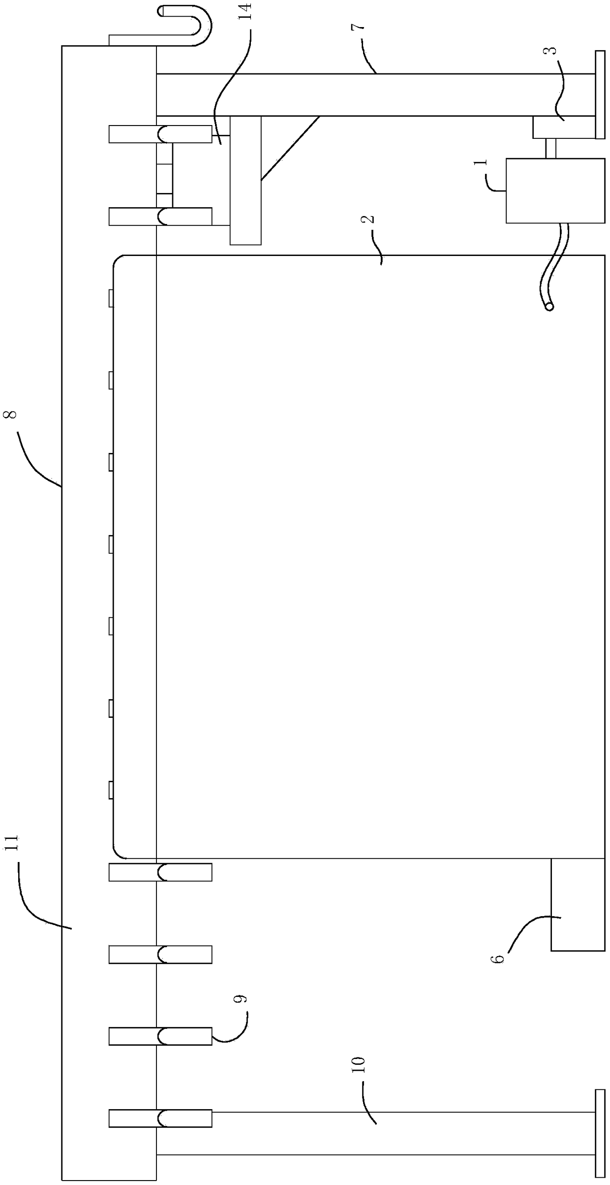
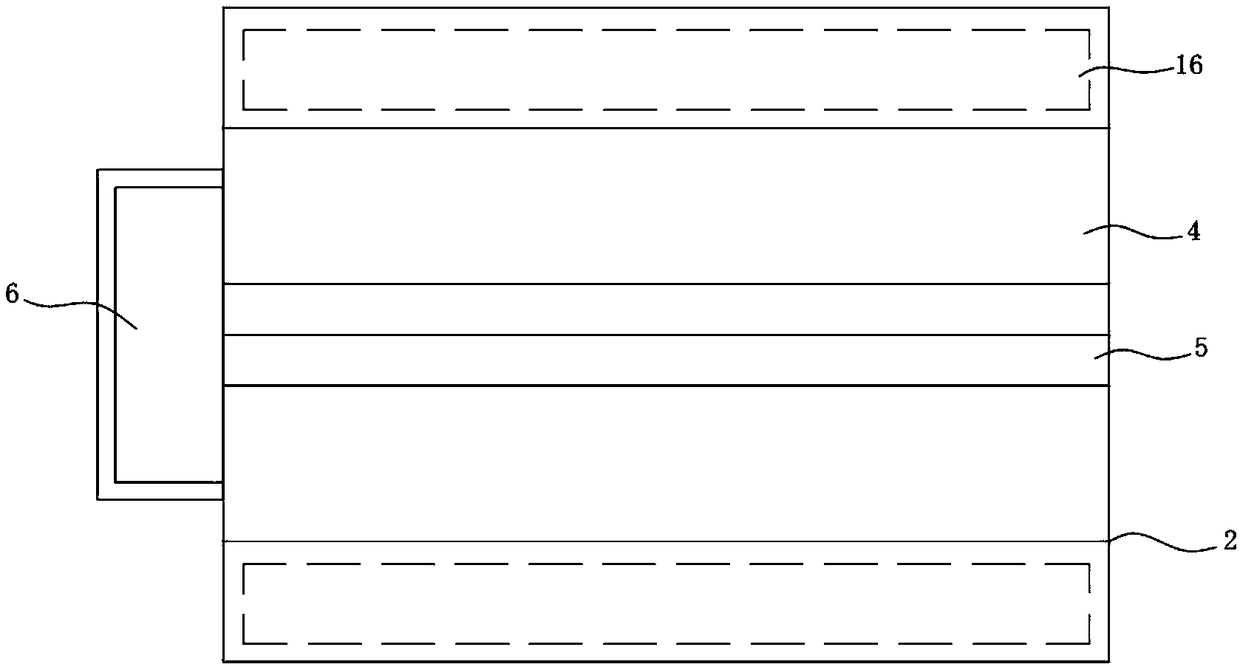
[0027] Such as figure 1 , figure 2 , image 3 , a casing dryer, comprising an air heating chamber 1 and a drying chamber 2, the air heating chamber 1 is supplied with air by an air pump 3, and the drying chamber 2 includes a drying channel 4, the upper end of which is open, and the The side walls of the drying passage 4 are evenly distributed with air jet holes, which are used to eject airflow on the one hand, and on the other hand, the air jet holes can guide the airflow so that the airflow blows to the casing at a reasonable angle to improve the casing casing. drying efficiency.

[0028] Such as figure 1 , figure 2 , image 3 , the air injection hole communicates with the air heating chamber 1, the air heated by the air heating chamber 1 is blown to the drying passage 4 through the air injection hole, and the air heating chamber 1 is provided with a heating air heating chamber 1 The heating tube can be a tubular structure with heating function such as an electric hea...

Embodiment 2

[0033] This embodiment introduces the structure of the transport frame 7 in combination with Embodiment 1.

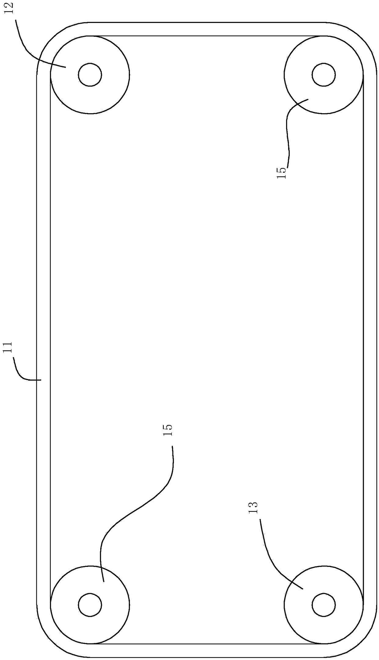
[0034] Such as figure 1 , image 3 , the conveying frame 7 includes a frame body 10, the rotary mechanism 8 is fixed on the frame body 10, the rotary mechanism 8 includes a timing belt 11 that rotates on the frame body 10, and the hook 9 is fixed on On the synchronous belt 11, and one side of the synchronous belt 11 is located in the drying channel 4, the rotary mechanism 8 also includes a driving pulley 12 and a driven pulley 13 matched with the synchronous belt 11, The driving pulley 12 is driven to rotate by the motor 14, the driving pulley 12 and the driven pulley 13 are both rotatably connected to the frame body 10, and the slewing mechanism 8 also includes a The auxiliary wheel 15 on the top, the auxiliary wheel 15 cooperates with the synchronous belt 11. The effect of the auxiliary wheel 15 is to make the synchronous belt 11 have a reasonable movement track, s...

Embodiment 3

[0038] This embodiment introduces the fixing method of the hook 9 and the timing belt 11 .

[0039] The hook 9 is fixed on the timing belt 11 by screws.

[0040] Alternatively, the hook 9 is bonded to the timing belt 11 .

[0041] Alternatively, the hook 9 is hooked on the timing belt 11 .

[0042] The hook 9 can be fixed on the synchronous belt 11 by any method, and the specific fixing method can be freely selected by those skilled in the art, and is not limited here.


PUM


Abstract

The invention relates to sausage casing processing equipment, in particular to a sausage casing dryer and belongs to the field of sausage casing processing. The sausage casing dryer is reasonable in structure design and convenient to operate by an operator. According to the sausage casing dryer, an air heating chamber heats air pumped by an air pump, the heated air enters a drying chamber and is blown to a drying channel through a blowhole, the sausage casings pass through the drying channel under the action of a swing mechanism, the air flow exhausted by the blowhole dries the sausage casingsrapidly, and the sausage casing drying efficiency is improved. Hooks are arranged on the swing mechanism and used for hanging the sausage casings, during actual operation, the operator only needs tohang the undried sausage casings on the hooks, then the dried sausage casings are taken down from the hooks, the labour intensity of the operator is reduced, and the sausage casing drying operation isconvenient.

Description

technical field [0001] The invention relates to casing processing equipment, in particular to a casing dryer and belongs to the field of casing processing. Background technique [0002] Casing is a product of large intestine or small intestine. The casing needs to go through a cleaning process in the process of processing to clean the stains on the casing. After cleaning the casing, the casing needs to be dried. There are two methods of drying the casing in the prior art, one is the natural drying method , this drying method takes a long time and reduces the processing efficiency of casings. [0003] Another method of drying casings is forced drying, that is, blowing air to the casings through a fan, so that the casings can be dried quickly. This drying method has high efficiency, but the device structure of the forced drying casing in the prior art is unreasonable, which is not conducive to the operation of the operator and increases the labor intensity of the operator. ...

Claims


Application Information

Patent Timeline
Patent Type & Authority Applications(China)
IPC IPC(8): F26B15/12F26B21/00F26B21/10F26B25/00A22C13/00
CPCA22C13/00F26B15/12F26B21/001F26B21/004F26B21/10F26B25/00F26B25/003
Inventor 黄金桥黄闰庚周林生沈红霞黄剑刚黄志有孟生高
Owner 浙江亚泰生物科技有限公司
Why Eureka
Try Eureka