Flour bran heat pump drying device

A heat pump drying and bran technology, which is applied in the direction of drying gas arrangement, drying solid materials, drying granular materials, etc., can solve the problems of difficult control of drying quality, unfavorable popularization and application, complicated equipment, etc., and achieves precise control of drying temperature and is easy to promote Application, the effect of improving drying efficiency

Pending Publication Date: 2018-11-23
HENAN BAIHENG ENERGY SAVING TECH
View PDF4 Cites 2 Cited by
  • Summary
  • Abstract
  • Description
  • Claims
  • Application Information

AI Technical Summary

Problems solved by technology

The disadvantages of this technology are: the heat is transferred to the outer wall through the medium and then transferred to the flour, the heat utilization efficiency is low, and the drying efficiency is low; and when the temperature of the heat transfer medium is low, the drying is not sufficient, and the flour is easy to change color and deteriorate when the temperature of the heat transfer medium is high. The drying quality of flour is poor, and the drying quality is difficult to control; at the same time, the equipment is relatively complex and takes up a lot of space; usually the heating element is electric heating, which increases the burden on users and is not conducive to large-scale promotion and application across the country.

Method used


Image

  • Flour bran heat pump drying device
  • Flour bran heat pump drying device
  • Flour bran heat pump drying device

Examples


Embodiment Construction

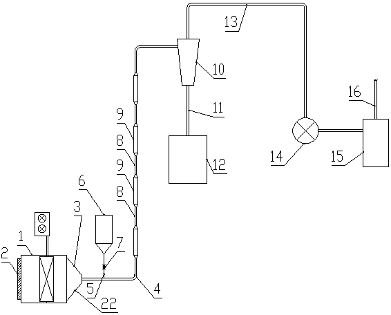
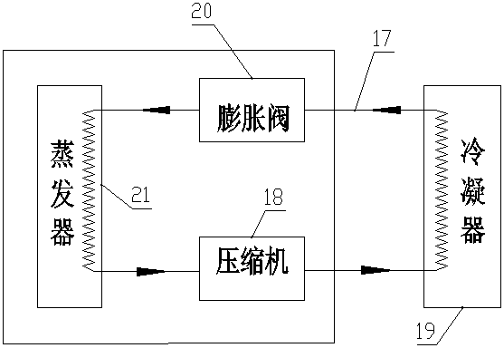
[0022] Such as Figure 1 to Figure 3 As shown, the flour bran heat pump drying device of the present invention comprises a heat pump system and a heating chamber 1; the air inlet of the heating chamber 1 is provided with an air filter 2, and the air outlet 3 of the heating chamber 1 is connected with an air supply pipe 4; For the downstream direction, the upstream end of the air supply pipe 4 is connected with a feed pipe 5, and the feed pipe 5 is upwardly connected with a raw powder storage tank 6 for storing the raw powder of flour bran, and the feed pipe 5 is provided with a feed valve 7;

[0023] The air supply pipe 4 in the downstream direction of the feed pipe 5 is connected in series with some speed-up pipe sections 8 and some deceleration pipe sections 9, the pipe diameter of the speed-up pipe sections 8 is smaller than the deceleration pipe sections 9, and the speed-up pipe sections 8 and the deceleration pipe sections 9 are arranged alternately; The speed increase p...


PUM


Abstract

The invention discloses a flour bran heat pump drying device which comprises a heat pump system and a heating chamber. A wind outlet of the heating chamber is connected with a wind supply pipe. The flowing direction of wind is the downstream direction. The upstream end portion of the wind supply pipe is connected with a feeding pipe. The feeding pipe is connected with a raw powder storing tank used for storing raw powder of flour bran upwards. The feeding pipe is provided with a discharging valve. A wind supply pipe in the downstream direction of the feeding pipe is connected with a pluralityof speed increase pipe sections and a plurality of speed reduction pipe sections in series. The speed increase pipe sections and the speed reduction pipe sections are arranged in an alternating manner. A wind supply pipe in the downstream direction of a variable speed drying area is connected with a cyclone separator. The bottom end of the cyclone separator is connected with a dry powder storing tank. The top end of the cyclone separator is connected with a wind inlet of a fan. When airflow carrying powder passes through the variable speed drying area, the speed difference is kept between theairflow speed and the raw powder particle speed, the heat exchange speed between the raw powder particles and hot wind is increased, water in flour can be evaporated fast, and the drying efficiency isimproved. By the adoption of a heat pump, the drying device has the characteristics of being efficient and environmentally friendly, and saving energy.

Description

technical field [0001] The invention relates to the field of heat pump drying equipment, in particular to the technical field of drying equipment for powdery and small particle products, and is especially suitable for drying equipment for materials such as flour and bran. Background technique [0002] When the moisture content in the flour is too high, mildew and agglomeration are prone to occur, resulting in shortened shelf life, uneven product quality, and inconvenient long-distance transportation and sales of finished products. In order to solve this problem, all flour manufacturers are constantly looking for energy-saving and environment-friendly flour drying devices. [0003] After various experiments, the drying method of flour cannot be exposed to the sun. At present, some manufacturers adopt the method of installing a heat-conducting medium outside the flour conveying pipe, and the heat-conducting medium is equipped with a heating element. The disadvantages of this ...

Claims


Application Information

Patent Timeline
Patent Type & Authority Applications(China)
IPC IPC(8): F26B17/10F26B21/00F26B21/10F26B25/00
CPCF26B17/101F26B21/001F26B21/003F26B21/10F26B25/002F26B25/007F26B2200/08
Inventor 程烨殷宪春杨德亮李兴书李童李长彬
Owner HENAN BAIHENG ENERGY SAVING TECH
Why Eureka
Try Eureka