Device and method for measuring radial run-out of roller part based on synchronous belt drive
A technology of radial runout and measuring device, applied in measuring devices, instruments, etc., can solve problems such as large error and unstable reading acquisition, and achieve the effects of stable mechanism, fast measurement, and high measurement accuracy
- Summary
- Abstract
- Description
- Claims
- Application Information
AI Technical Summary
Problems solved by technology
Method used
Image

Examples
Embodiment Construction
[0033] The device and method for measuring radial runout of workpieces based on synchronous belt-driven rollers according to the present invention will be described in detail below in conjunction with the embodiments and accompanying drawings.
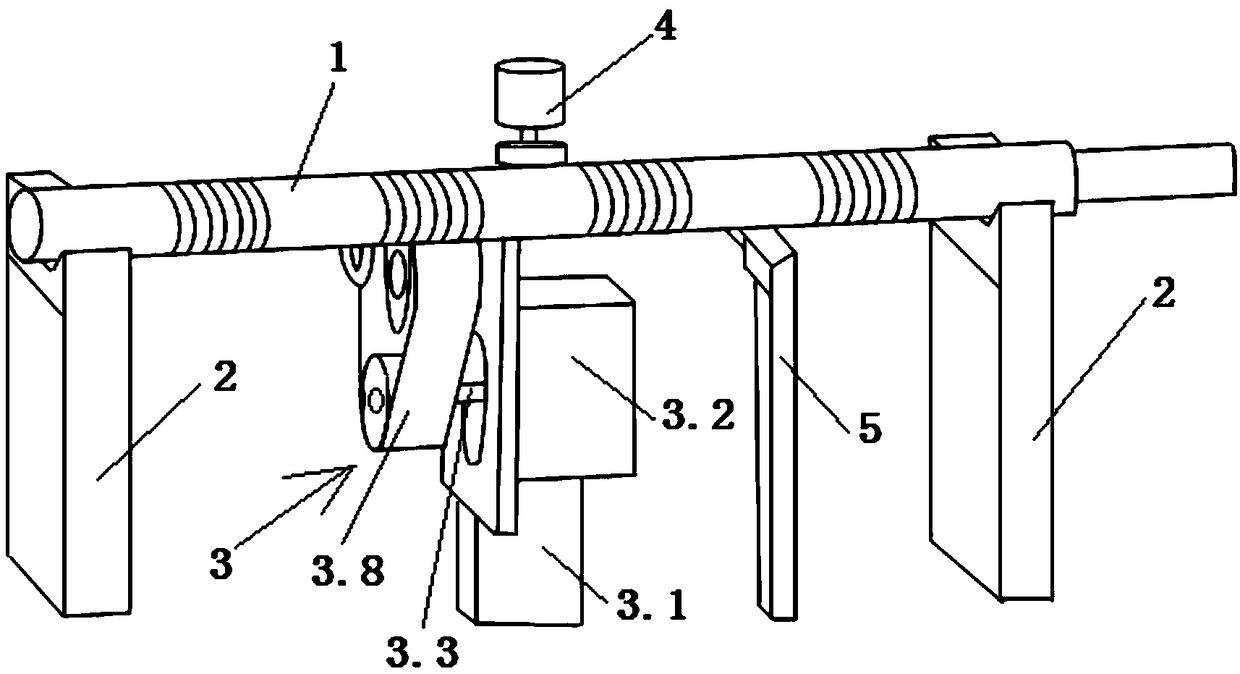
[0034] Such as figure 1 As shown, the radial runout measuring device based on the synchronous belt driven roller workpiece of the present invention includes two V-shaped support frames 2 for supporting the two ends of the roller workpiece 1 respectively, and a roller workpiece for driving the roller workpiece is arranged in the middle part of the lower side of the roller workpiece 1. 1 rotating synchronous belt drive device 3, on the upper side of the roller workpiece 1, an elastic pressing device 4 for pressing the roller workpiece 1 to make the roller workpiece 1 rotate stably, and on the lower side of the roller workpiece 1, is provided with a measuring roller workpiece 1 A flex gauge sensor 5 for radial runout, the signal output en...
PUM
 Abstract
Description
Claims
Application Information