
Multifunctional rail grinding test device

A test device and multi-functional technology, applied in the field of multi-functional rail grinding test device, can solve problems such as short service life, unfavorable analysis of workpieces, backward technology, etc., and achieve improved stability and repeatability, thick and stable lathe structure, The effect of saving working time

Pending Publication Date: 2018-11-23
SOUTHWEST JIAOTONG UNIV
View PDF0 Cites 2 Cited by
  • Summary
  • Abstract
  • Description
  • Claims
  • Application Information

AI Technical Summary

Problems solved by technology

[0003] The development of rail grinding and maintenance technology in China is relatively late, and the technology is relatively backward. Although my country has made great progress in the traditional active rail grinding train technology, it is still in the exploratory stage for rail grinding strategies and programs. At the same time, only a few countries such as Germany have mastered the high-speed passive rail grinding technology. my country currently has very little technology accumulation in this area, and there is another fact that cannot be ignored, that is, rail At present, our country relies heavily on imports for the grinding wheels for grinding trains. The reason is that the performance of the domestically produced grinding wheels is uneven, the grinding ability is weak, and the service life is short. Therefore, it is necessary to study the grinding principle of rail grinding. Parameters (grinding pressure, grinding stone speed, grinding speed, etc.), grinding wheel parameters (abrasive type, abrasive ratio, abrasive particle size, abrasive concentration, bond strength, filler type, etc.) Provide a theoretical basis for grinding efficiency and better rail surface quality, and also provide theoretical guidance for the development of rail grinding wheels
[0004] At present, the rail grinding test can be carried out on-site on the test line or on the test bench in the laboratory. Although the results of the on-site rail grinding test are the most reliable, the cost of the on-site rail grinding test is high, the cycle is long, and the grinding process The collection of data is also inconvenient, and the test equipment in the laboratory is basically designed for a single grinding stone, and the large workpiece is not conducive to subsequent analysis, and it is not convenient for further analysis of the grinding mechanism and evaluation of the performance of the grinding wheel. To this end, we propose a multifunctional rail grinding test device

Method used


Image

  • Multifunctional rail grinding test device
  • Multifunctional rail grinding test device
  • Multifunctional rail grinding test device

Examples


Embodiment 1

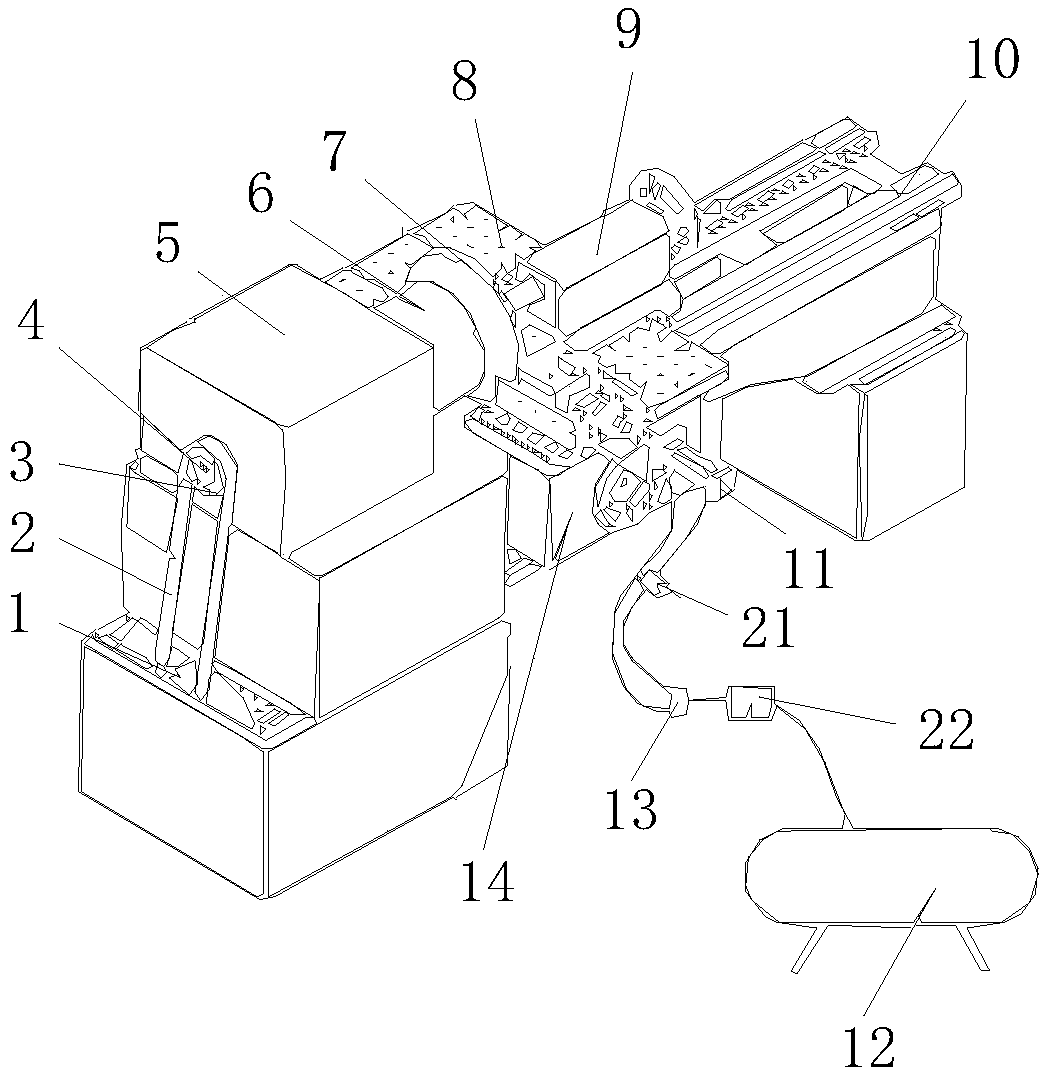
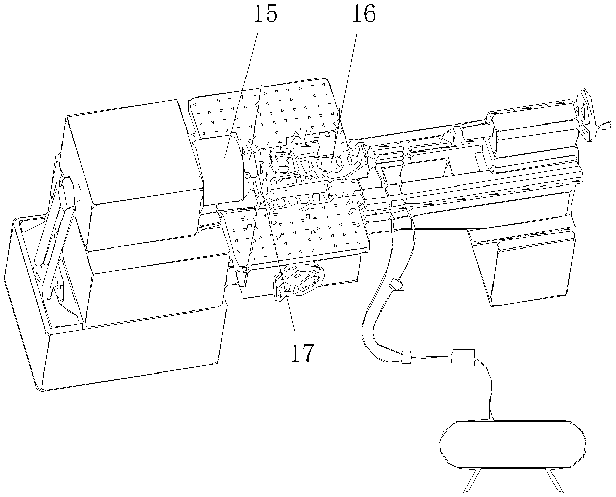
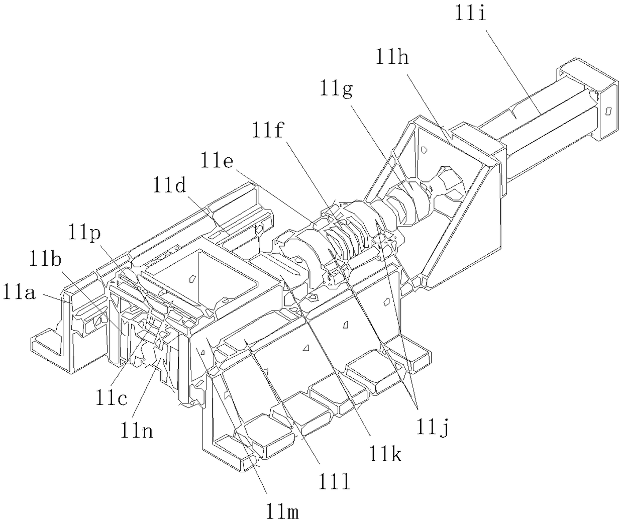
[0023] see figure 1 , image 3 and Figure 5, a multifunctional rail grinding test device, comprising a lathe main shaft 4, a workbench 8, an actuating device 11, an air compressor 12, a grinding wheel sample 19 and a frequency conversion motor 1 installed in a lathe motor box, the frequency conversion motor 1 The output shaft of the output shaft is equipped with a synchronous pulley 3, and is connected with the synchronous pulley 3 of the lathe spindle 4 through the synchronous belt 2, the lathe spindle 4 is fixed by the lathe spindle box 5 and the other end is equipped with a three-jaw chuck 6, and a three-jaw chuck 6 The outer surface of the disc is movably connected with a disc-shaped rail workpiece 7 and a rail grinding wheel 15. The disc-shaped rail workpiece 7 is to intercept a whole piece of material from a billet. After processing, the same measures as the rail heat treatment process are carried out. The workpiece 7 has the same mechanical properties and microstruct...

Embodiment 2

[0025] see figure 2 , image 3 and Figure 4 , a multifunctional rail grinding test device, comprising a lathe main shaft 4, a workbench 8, an actuating device 11, an air compressor 12, a grinding wheel sample 19 and a frequency conversion motor 1 installed in a lathe motor box, the frequency conversion motor 1 The output shaft of the output shaft is equipped with a synchronous pulley 3, and is connected with the synchronous pulley 3 of the lathe spindle 4 through the synchronous belt 2, the lathe spindle 4 is fixed by the lathe spindle box 5 and the other end is equipped with a three-jaw chuck 6, and a three-jaw chuck 6 The outer surface of the disc is movably connected with a disc-shaped rail workpiece 7 and a rail grinding wheel 15. The disc-shaped rail workpiece 7 is to intercept a whole piece of material from a billet. After processing, the same measures as the rail heat treatment process are carried out. The workpiece 7 has the same mechanical properties and microstru...


PUM


Abstract

The invention discloses a multifunctional rail grinding test device, including a lathe spindle, a workbench, an actuator, an air compressor, a grinding wheel specimen, and a variable frequency motor arranged in a lathe motor case. An output shaft of the variable frequency motor is provided with a synchronous pulley, and the synchronous pulley is connected with a synchronous pulley of the lathe spindle through a synchronous belt. The lathe spindle is fixed via a lathe spindle box, and the other end of the lathe spindle is provided with a three-jaw chuck. The external surface of the three-jaw chuck is movably connected with a disc-shaped rail workpiece and a rail grinding wheel, the other end of a central shaft of the disc-shaped rail workpiece is movably connected with a lathe tail seat, and the bottom of the lathe tail seat is fixedly connected with a lathe body. The workbench is connected with a sliding box through bolts. The multifunctional rail grinding test device can simulate different rail grinding modes, can carry out polishing tests of different polishing pressures, rotational speeds and grinding wheel parameters, provides convenience for exploring a rail polishing mechanism, provides a certain theoretical basis for on-site rail polishing, and provides theoretical guidance for the development of grinding stones.

Description

technical field [0001] The invention relates to the technical field of grinding wheel grinding test devices, in particular to a multifunctional rail grinding test device. Background technique [0002] Rail is an important load-bearing component of the railway system. During the service process, it will inevitably produce many defects such as corrugation, bruises, cracks, fat edges, etc. At present, rail grinding trains are mainly used to maintain rails on the line. There are two types of rail grinding trains and passive high-speed rail grinding trains. The traditional rail grinding train drives the grinding wheel to rotate at high speed through a motor and uses a hydraulic device to load the grinding wheel. At the same time, the grinding train runs at a certain speed (maximum 18km / h) , so as to achieve the purpose of removing rail surface defects. The high-speed passive grinding vehicle contacts the circumferential surface of the grinding wheel with the rail with a certain l...

Claims


Application Information

Patent Timeline
IPC IPC(8): G01M99/00
CPCG01M99/005
Inventor 樊小强章武林张鹏飞贺继樊朱旻昊
Owner SOUTHWEST JIAOTONG UNIV
Learn More