Near-field electromagnetic wave measuring system and multifunctional near-field electromagnetic wave measuring method

A measurement system and electromagnetic wave technology, applied in measurement devices, material analysis using microwave means, instruments, etc., can solve the problem of single function of the measurement system, and achieve the effect of solving the high experimental cost and saving experimental time and space.

Active Publication Date: 2018-11-23
深圳凌波近场科技有限公司
View PDF7 Cites 5 Cited by
  • Summary
  • Abstract
  • Description
  • Claims
  • Application Information

AI Technical Summary

Problems solved by technology

[0006] The purpose of the present invention is to overcome the defects of the prior art. In order to solve the problem of single function of the measurement system, a near-field electromagnetic wave measurement system and a multifunctional near-field electromagnetic wave measurement method are proposed.

Method used


Image

  • Near-field electromagnetic wave measuring system and multifunctional near-field electromagnetic wave measuring method
  • Near-field electromagnetic wave measuring system and multifunctional near-field electromagnetic wave measuring method
  • Near-field electromagnetic wave measuring system and multifunctional near-field electromagnetic wave measuring method

Examples


Embodiment 1

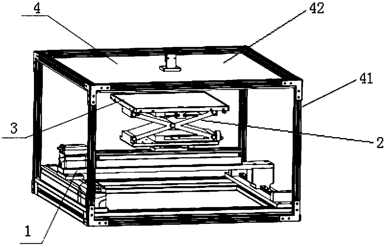
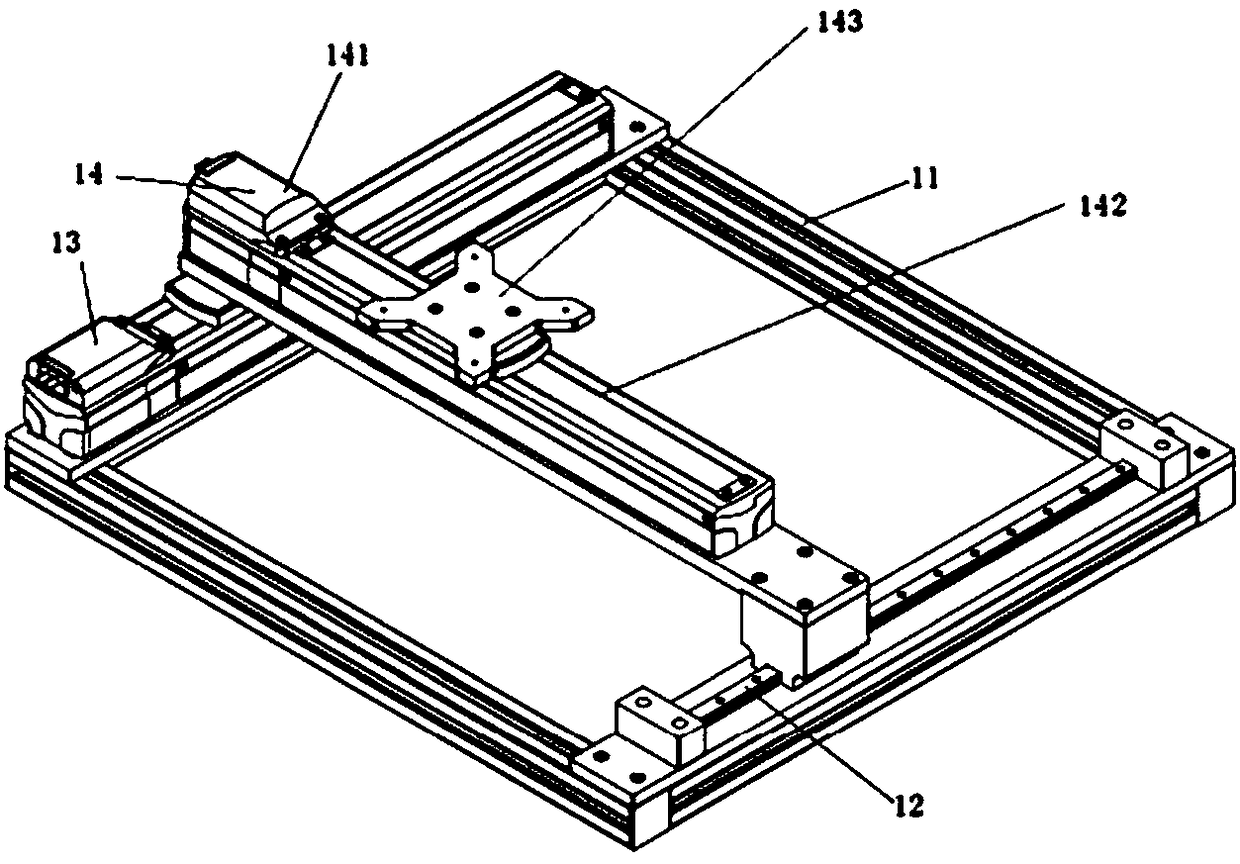
[0030] Such as figure 1 and 6 As shown, in this embodiment, the near-field microwave measurement system mainly includes a two-dimensional planar mobile system 1, a host computer, a vector network analyzer, a lifting platform 2, a level adjustment device 3, a near-field measurement probe and a detachable Upper board beam device 4,

[0031] The detachable upper plate beam device 4 includes an upper plate 42 and a frame 41; the upper plate is a metal plate; the sample is located between the upper plate and the level adjustment device. The frame is preferably made of non-metal, and the four side walls of the frame can use non-metal baffles or not, but metal baffles cannot be used.

[0032] Such as Figure 6As shown, the middle area of ​​the upper plate 42 is provided with a detection port 44, and the near-field measurement probe is clamped and fixed in the space above the sample by the line card 43 after passing through the detection port 44 on the detachable upper plate beam d...

Embodiment 2

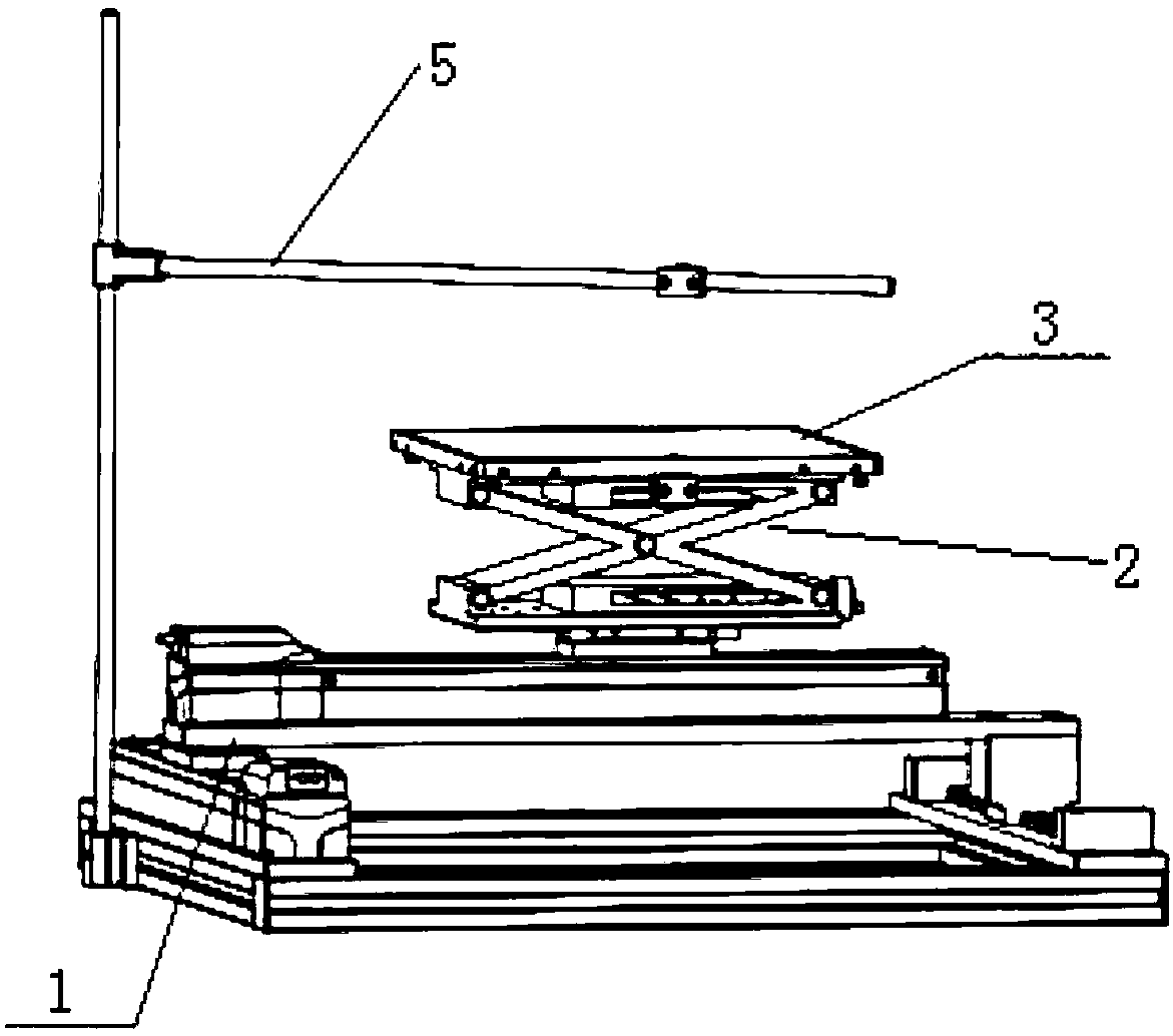
[0037] Such as figure 2 and Figure 5 As shown, the difference between Embodiment 2 and Embodiment 1 is that the detachable upper plate beam device 4 in Embodiment 1 is replaced by a detachable probe clamping device 5 . The near-field measurement probe is clamped and fixed in the space above the sample by a detachable probe clamping device, and the detachable probe clamping device is made of non-metallic material.

[0038] The detachable probe clamping device 5 includes a base fixing block 51, an optical axis 52, a support bar 54, a T-shaped connecting slider 53, and a cable clamp 55; the base fixing block and the two-dimensional plane moving system The base is fixedly connected, the base fixing block is connected to the optical axis, the optical axis and the support bar are connected through a T-shaped connecting slider, and the near-field measurement probe is clamped and fixed on the support bar through a cable clamp.

[0039] When measuring an open antenna sample, the st...

Embodiment 3

[0041] In this embodiment, the near-field microwave measurement system includes a detachable upper plate beam device 4 and a detachable probe clamping device 5, the detachable probe clamping device and the base of the two-dimensional plane moving system Connected; pulleys are installed at the bottom of the frame of the detachable upper plate beam device; the measuring probe is fixed by the cable clamp after passing through the cable clamp on the support cross bar, and the height of the measuring probe is located between the height of the upper plate and the height of the lower plate between.

[0042] The structures of the detachable upper plate beam device 4 and the detachable probe clamping device 5 can be shown as the corresponding component structures in Embodiments 1 and 2, respectively.

[0043] When performing open field measurement, just move the detachable upper plate beam device out of the measurement area;

[0044] When measuring the bound field, move the detachable...


PUM


Abstract

The invention discloses a near-field electromagnetic wave measuring system. The near-field electromagnetic wave measuring system comprises a two-dimensional plane moving system, a principal computer,a vector network analyzer, a lifting table, a horizontal adjusting apparatus and a near-field measuring probe; the principal computer is connected with the vector network analyzer, the input end of the vector network analyzer is connected with the near-field measuring probe, the output end is connected with a sample, and the sample is arranged on the horizontal adjusting apparatus; the horizontaladjusting apparatus is fixed on the lifting table; the lifting table is fixed on the two-dimensional plane coordinate moving system; and the near-field measuring probe is fixed in a space above the sample. The near-field electromagnetic wave measuring system not only can be used for measuring a waveguide (resonant cavity, photo crystal, negative refraction materials and the like) sample, but alsocan be used for measuring an antenna sample in an open environment, can be implemented by conveniently adjusting partial parts, can effectively solve the problem of excessively high experimental cost,can also be used for measuring various samples, and can also effectively save the experimental time and space.

Description

technical field [0001] The invention belongs to the technical field of microwave near-field measurement, and in particular relates to a near-field electromagnetic wave measurement system and a multifunctional near-field electromagnetic wave measurement method. Background technique [0002] Microwave near-field measurement technology has low environmental requirements, does not require an expensive darkroom environment, and does not require high requirements for radio frequency systems, and has low requirements for equipment. The data of the radiation field in the near-field area of ​​the sample is then transformed by the computer to deduce the far-field data from the near-field data. As long as the measurement accuracy is guaranteed, more accurate far-field characteristics can be obtained. [0003] The existing technical solution is that different samples need to use different measuring equipment and methods to scan and measure the amplitude and phase of the electromagnet...

Claims


Application Information

Patent Timeline
Patent Type & Authority Applications(China)
IPC IPC(8): G01N22/00
CPCG01N22/00Y02A90/30
Inventor 闫焕磊时西航许弘毅高振
Owner 深圳凌波近场科技有限公司
Why Eureka
Try Eureka