Rigid-flexible mixing optical fiber clamp with two-dimensional attitude adjustment function

A two-dimensional adjustment and hybrid technology, applied in the coupling of optical waveguides, optical guides, optics, etc., can solve the problems of high production cost of optical waveguide devices, increase the difficulty of optical fiber clamping, easy clamping and other problems, and achieve an increase of two Dimensional attitude adjustment function, convenient fiber clamping operation, with stable effect

Active Publication Date: 2018-11-23
BEIHANG UNIV
View PDF4 Cites 3 Cited by
  • Summary
  • Abstract
  • Description
  • Claims
  • Application Information

AI Technical Summary

Problems solved by technology

As mentioned above, the alignment requirements between the optical waveguide chip and the optical fiber are at the micron or sub-micron level, and it is necessary to use a high-precision motion platform to realize the adjustment of the position and orientation of the optical fiber. Precision motion platforms are mostly dependent on imports, resulting in high production costs for optical waveguide devices
In addition, due to the brittle material of lithium niobate, the existing optical fiber clamps have the disadvantages of being easily broken or not tightly clamped, which further increases the difficulty of optical fiber clamp design

Method used


Image

  • Rigid-flexible mixing optical fiber clamp with two-dimensional attitude adjustment function
  • Rigid-flexible mixing optical fiber clamp with two-dimensional attitude adjustment function
  • Rigid-flexible mixing optical fiber clamp with two-dimensional attitude adjustment function

Examples


Embodiment Construction

[0045] The present invention will be described in further detail below in conjunction with the accompanying drawings.

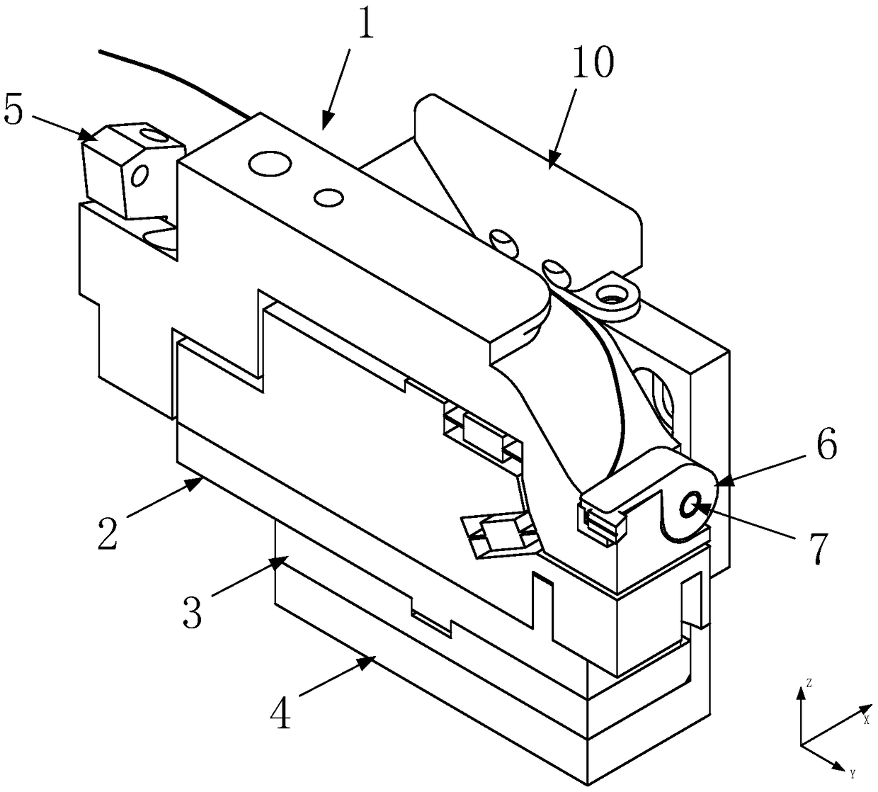
[0046] The present invention is a rigid-flexible hybrid optical fiber clamp with a two-dimensional attitude adjustment function, which is used for clamping polarization-maintaining optical fibers, and includes a two-dimensional adjustment structure 1, a deflection slide plate 2, a base slide plate 3, a fixed base 4, and a pressure adjustment block 5. The optical fiber pressing plate 6 and the connecting shaft 7 are assembled, such as figure 1 As shown, let the left-right direction be the x-axis, the front-back direction be the y-axis, and the vertical direction be the z-axis.

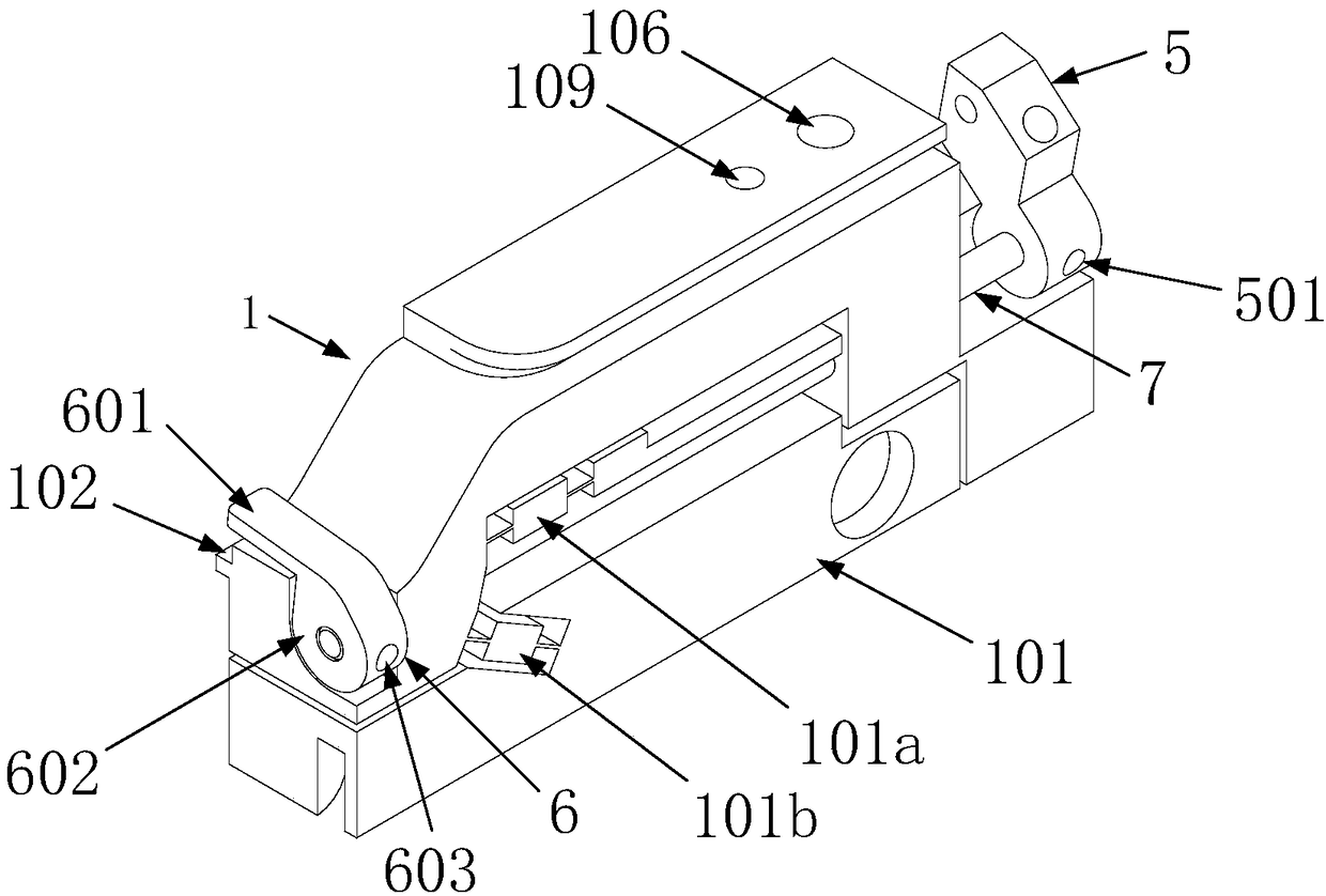
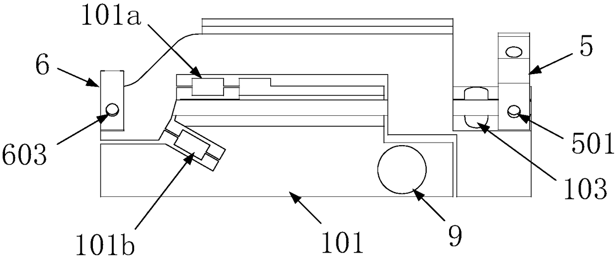
[0047] The two-dimensional adjustment structure 1, the pressure adjustment block 5, the optical fiber pressure plate 6 and the connecting shaft 7 serve as the main body of the optical fiber clamp of the present invention, such as figure 2shown. Wherein, the lower part of the two-dim...


PUM


Abstract

The present invention discloses a rigid-flexible mixing optical fiber clamp with a two-dimensional attitude adjustment function. The rigid-flexible mixing optical fiber clamp comprises a two-dimensional adjustment structure, a rack is arranged at the inner concave of the lower portion of the clamp, an optical fiber putting groove is designed at the end portion of the front end of the clamp, an optical fiber pigtail block is arranged in the groove and is compacted by an optical fiber pressing plate, and the pressure of the optical fiber pressing plate is adjustable. The rack is connected with the two-dimensional adjustment structure through a flexible hinge to allow the pitching angle of the two-dimensional adjustment structure to be adjustable; the lower portion of the rack is provided with a deflection sliding plate, and the rack and the deflection sliding plate can be relatively rotated to achieve adjustment of the deflection angle of the two-dimensional adjustment structure. The lower portion of the deflection angle is provided with a fixing mechanism to achieve connection between the fixing mechanism and a waveguide chip coupling displacement bench. Long circular holes are arranged on the deflection sliding plate, a fixed substrate and a substrate sliding plate in X, Y and Z directions to achieve position regulation of the two-dimensional adjustment structure on a triaxialdirection. The rigid-flexible mixing optical fiber clamp can flexibly adjust the optical fiber clamping pressure and the installation position of the optical fiber clamp, and a serial three-dimensional translation platform with a two-dimensional attitude adjustment function and a one-dimensional rotation table can achieve six-dimensional pose adjustment of the optical fiber.

Description

technical field [0001] The invention relates to an optical fiber clamp, in particular to a rigid-flexible hybrid optical fiber clamp with a two-dimensional attitude adjustment function. Background technique [0002] Integrated optical waveguide device, referred to as optical waveguide device, is an optical device based on waveguide optics theory and microelectronic processing technology. Due to its small size and high density, it is widely used in optical fiber communication, optical fiber sensing and other fields. [0003] The manufacture of optical waveguide devices mainly includes the manufacture of optical waveguide chips and the coupling and packaging of optical waveguide devices. The coupling package of the optical waveguide device is divided into the pose alignment of the waveguide chip and the optical fiber and the fixed connection after alignment. The pose alignment between the waveguide chip and the optical fiber needs to install and clamp the optical fiber on the...

Claims


Application Information

Patent Timeline
Patent Type & Authority Applications(China)
IPC IPC(8): G02B6/36
CPCG02B6/3616
Inventor 贾明武立勇宋凝芳
Owner BEIHANG UNIV
Why Eureka
Try Eureka