
Method and system for achieving edge enhancement imaging

An edge enhancement and imaging technology, which is applied in the direction of optical components, optics, instruments, etc., can solve the problems of uneven results, diffraction noise of imaging results, and poor realization of phase equivalence.

Active Publication Date: 2018-11-23
SUZHOU UNIV
View PDF12 Cites 13 Cited by
  • Summary
  • Abstract
  • Description
  • Claims
  • Application Information

AI Technical Summary

Problems solved by technology

[0003] In 2018, Zhu Tengfeng used the surface plasmon structure to achieve spatial differential edge-enhanced imaging in experiments, but this digital imaging technology cannot achieve phase alignment well when the object has no obvious features.
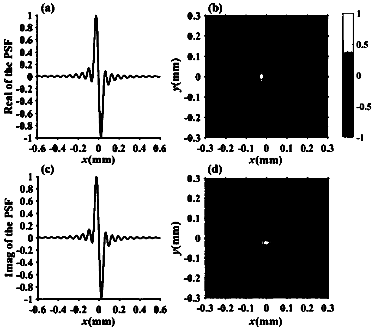
However, we found that there are a large number of redundant side lobes on both sides of the main lobe of the point spread function of the traditional vortex phase plate. This phenomenon will cause diffraction noise at the edge of the imaging result, making the result uneven, and this effect will be becomes severe with increasing topological sum

Method used


Image

  • Method and system for achieving edge enhancement imaging
  • Method and system for achieving edge enhancement imaging
  • Method and system for achieving edge enhancement imaging

Examples


Embodiment Construction

[0043] The present invention will be further described below in conjunction with the accompanying drawings and specific embodiments, so that those skilled in the art can better understand the present invention and implement it, but the examples given are not intended to limit the present invention.

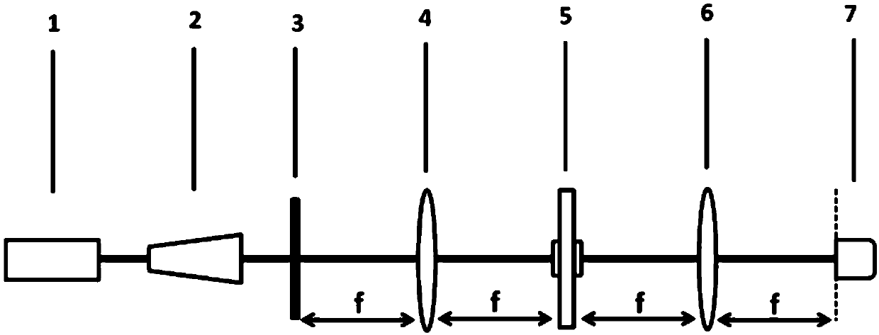
[0044] The method for realizing edge-enhanced imaging in the embodiment of the present invention includes the following steps:

[0045] S11, generating a Gaussian beam;

[0046] S12. Expanding and collimating the Gaussian beam, and projecting the expanded and collimated Gaussian beam onto an object;

[0047] Specifically, the Gaussian beam is expanded and collimated by a beam expander.

[0048] S13. Performing a first Fourier transform on the light beam passing through the object;

[0049] Specifically, a first Fourier transform is performed on the light beam passing through the object through the first Fourier lens.

[0050] S14. Modulating the light beam after the first Fouri...


PUM


Abstract

The invention discloses a method and system for achieving the edge enhancement imaging, and the method comprises the steps: projecting an expanded beam and a collimated Gaussian beam to an object; carrying out the first Fourier transform of the beam passing through the object, modulating the beam after the first Fourier transform, performing the second Fourier transform of the modulated beam and then performing imaging, wherein the obtaining process of a filtering function for modulating the beam comprises the following steps: combining the modulation effect of the amplitude and phase for theedge enhancement imaging, and superposing four Gaussian functions to obtain a point diffusion function, wherein a condition that there is no surplus sidelobe around a main lobe is met; performing thereverse calculation of the point diffusion function through the Fourier transform, thereby achieving the high-resolution and isotropic edge enhancement imaging in a Fourier plane of a second Fourier lens.

Description

technical field [0001] The present invention relates to the technical field of edge-enhanced imaging, in particular to a method and system for realizing edge-enhanced imaging. Background technique [0002] Edge-enhanced imaging technology has great applications in the field of imaging. In 1942, Zernike realized phase contrast imaging for the first time. Since then, a lot of work has been used to study this technology. Marr and Torre et al. Imaging has a big contribution. At present, the techniques commonly used to achieve edge-enhanced imaging mainly include ① numerical space differential imaging, ② differential interference contrast imaging, and ③ Hilbert transform filter imaging. [0003] In 2018, Zhu Tengfeng used the surface plasmon structure to achieve spatially differential edge-enhanced imaging in experiments, but this digital imaging technology cannot achieve phase pairing well when the object has no obvious features. The differential interference contrast imaging ...

Claims


Application Information

Patent Timeline
IPC IPC(8): G02B27/00G02B27/30G02B27/09
CPCG02B27/00G02B27/0927G02B27/30
Inventor 姚海南王飞蔡阳健
Owner SUZHOU UNIV
Learn More