Time-delay inertial microfluidic power connection switch

A technology of microfluidics and electric switches, applied in the direction of electric switches, circuits, electrical components, etc., can solve the problems of microfluidic droplet separation, delay time cannot be accurately controlled, and reduce the reliability of switches, so as to achieve low production costs and reduce Droplet Separation, Contact Reliable Effects

Active Publication Date: 2018-11-23
NANJING UNIV OF SCI & TECH
View PDF7 Cites 2 Cited by
  • Summary
  • Abstract
  • Description
  • Claims
  • Application Information

AI Technical Summary

Problems solved by technology

However, this switch also has disadvantages, such as the flow mode of the working fluid of the switch is similar to jet flow, the delay time cannot be precisely controlled, and the separation of microfluidic droplets is prone to occur, which reduces the reliability of the switch.

Method used


Image

  • Time-delay inertial microfluidic power connection switch
  • Time-delay inertial microfluidic power connection switch
  • Time-delay inertial microfluidic power connection switch

Examples


Embodiment Construction

[0026] In order to illustrate the technical scheme and technical purpose of the present invention, the present invention will be further introduced below in conjunction with the accompanying drawings and specific embodiments.

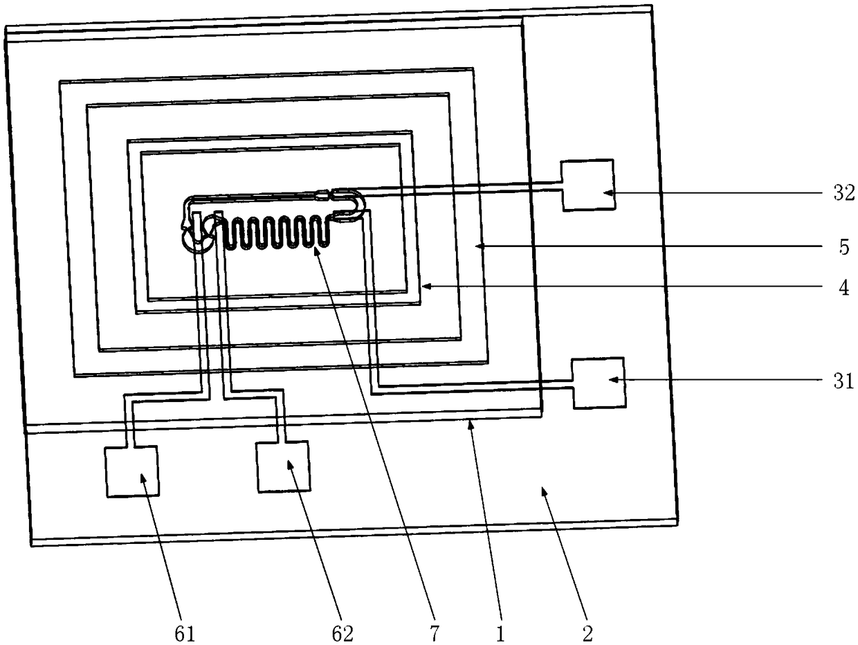
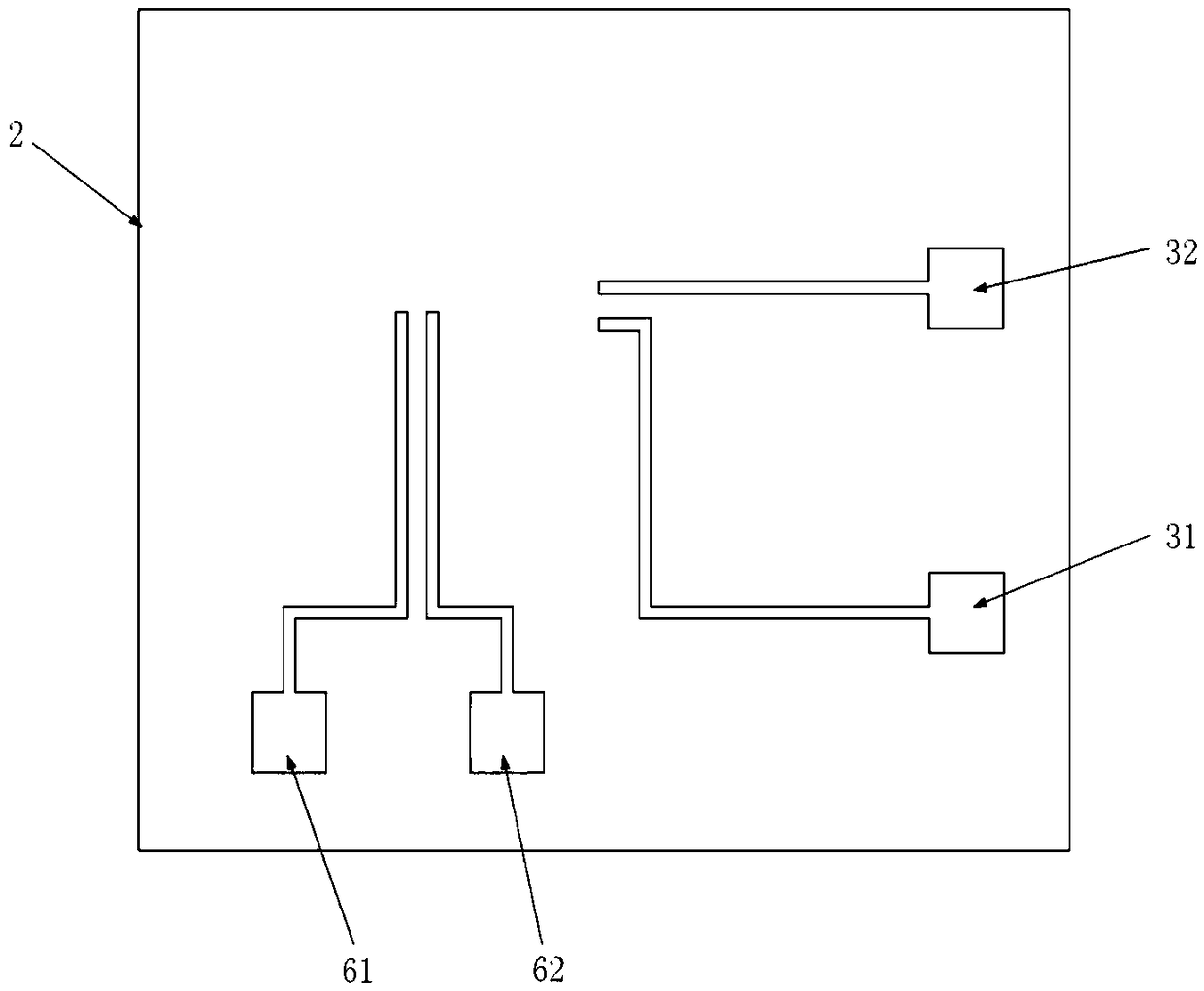
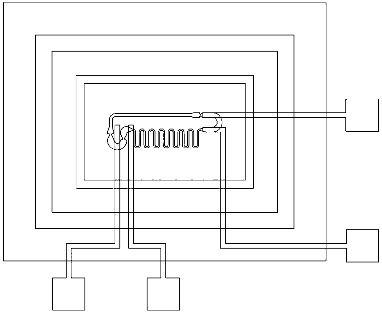
[0027] combine Figure 1-Figure 4 , a time-delayed inertial microfluidic power switch of the present invention includes a base 1, a cover plate 2, a microchannel 7, a metal droplet, a first electrode 31, and a second electrode 32; the microchannel 7 is arranged on the base 1; the seal between the base 1 and the cover plate 2 prevents metal droplets from splashing out of the microchannel 7; the microchannel 7 includes a J-shaped liquid reservoir 8, a first capillary valve 9, and a second capillary valve 10. The third capillary valve 13, the fourth capillary valve 14, the fifth capillary valve 16, the sixth capillary valve 18, the seventh capillary valve 19, the eighth capillary valve 21, the ninth capillary valve 26, the tenth capillary valve 25, The el...


PUM


Abstract

The invention discloses a time-delay inertial microfluidic power connection switch, belonging to the field of microfluidic chips, comprising a substrate, a cover plate, four metal electrodes, a microchannel and metal droplets. The cover plate is arranged at the upper end of the substrate, and sealing is formed between the cover plate and the substrate; the microchannel is formed in the substrate;and the metal electrodes are arranged on the cover plate. The microchannel comprises a J-shaped liquid reservoir, a capillary valve, a straight channel, a time-delay channel, a U-shaped blocking channel and an air guide channel. The metal droplets are located in the J-shaped liquid reservoir. One end contacts of the four metal electrodes are located in the microchannel, and the other end contactsare located outside the overlap region of the substrate and the cover plate. When the inertial force applied to the switch is greater than a threshold value, the metal droplets flow through the capillary valve to the time-delay channel for time delay, and finally flow to the metal electrodes under the action of the inertial force, and the switch is on. The time-delay inertial microfluidic power connection switch has a simple structure, a stable and reliable contact, and an accurate time-delay function compared with the existing microfluid inertial switch.

Description

technical field [0001] The invention belongs to the technical field of microfluidic chips, in particular to a time-delayed inertial microfluidic power switch. Background technique [0002] The microfluidic inertia switch is a new type of switch proposed on the basis of micromechanical inertial switch and microfluidic technology. The basic structure of a traditional micromechanical inertia switch is usually composed of a cantilever beam and a spring-mass system, and the conduction of the switch is based on "solid-solid contact". Microfluidic inertial switches generally use liquid metal as the working fluid. When the switch is subjected to an acceleration greater than its threshold, the working fluid will move to the position of the metal electrode, and then turn on the switch. The "solid-solid contact" mode of the traditional micromechanical inertia switch has the disadvantages of large on-resistance, poor anti-interference ability, unstable contact, and wear and tear of met...

Claims


Application Information

Patent Timeline
IPC IPC(8): H01H29/00
CPCH01H29/002
Inventor 聂伟荣刘国伟李嘉杰
Owner NANJING UNIV OF SCI & TECH
Why Eureka
Try Eureka