
A kind of rotary etching device and wet etching machine table

An etching device and wet etching technology, which is applied in the manufacture of electrical components, circuits, semiconductors/solid-state devices, etc., can solve the problems of reduced chemical solution etching rate, poor wafer uniformity, and low wafer edge etching rate, etc. , to achieve the effect of increasing the etching rate, changing the uniformity, and reducing the risk of scrapping

Active Publication Date: 2020-11-03
WUHAN XINXIN SEMICON MFG CO LTD
View PDF3 Cites 0 Cited by
  • Summary
  • Abstract
  • Description
  • Claims
  • Application Information

AI Technical Summary

Problems solved by technology

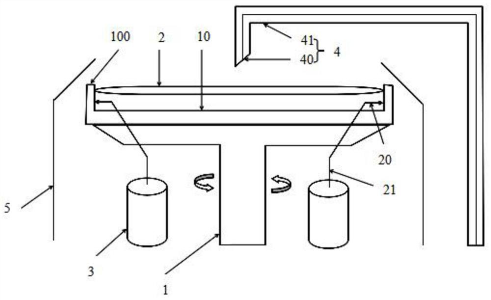
[0003] During the etching process of the rotary etching device of the wet etching machine, the wafer is in a state of high-speed rotation, and the chemical solution used for etching is evenly dispersed from the center of the wafer to the edge of the wafer. As the distance from the center of the circle increases, the chemical solution will gradually increase under the centrifugal force, and the content of the chemical solution spread in the unit area will gradually decrease, causing the etching rate of the chemical solution to decrease gradually with the increase of the radius. The swing of the liquid delivery pipeline can make the chemical solution diffuse to the edge of the wafer, but the liquid delivery pipeline cannot swing to the extreme edge of the cavity, and the current maximum position is 90% of the wafer, which causes the edge of the wafer on the rotary etching device to The etch rate is low, resulting in poor uniformity of the entire wafer, and the thickness at the edge of the wafer makes the final wafer product etched unevenly, so that the uniformity of the entire wafer cannot be improved

Method used


Image

  • A kind of rotary etching device and wet etching machine table

Examples


Embodiment Construction

[0025] The following will clearly and completely describe the technical solutions in the embodiments of the present invention with reference to the accompanying drawings in the embodiments of the present invention. Obviously, the described embodiments are only some, not all, embodiments of the present invention. Based on the embodiments of the present invention, all other embodiments obtained by persons of ordinary skill in the art without creative efforts fall within the protection scope of the present invention.

[0026] It should be noted that, in the case of no conflict, the embodiments of the present invention and the features in the embodiments can be combined with each other.

[0027] The present invention will be further described below in conjunction with the accompanying drawings and specific embodiments, but not as a limitation of the present invention.

[0028] The present invention includes a spin etching device, which is suitable for semiconductor wet etching pro...


PUM


Abstract

The invention discloses a rotary etching device and a wet etching machine, which are suitable for a semiconductor wet etching process, comprising: a supporting structure, which provides a supporting surface for supporting a wafer to be etched; A predetermined distance is preset between the wafer and the support surface, and a plurality of gas nozzles are evenly distributed on the support surface facing the wafer to be etched; the temperature control heating device is connected to the gas pipeline of the gas nozzle on the edge to heat the gas The protective gas in the pipeline; the nozzle device is arranged above the support surface. The nozzle device includes a nozzle and a liquid delivery pipe. The nozzle is arranged on the side facing the support surface. The liquid delivery pipe is connected to the end of the nozzle facing away from the support surface. Beneficial effects: by adding a temperature control heating device to heat the protective gas, the edge temperature of the wafer is changed, thereby increasing the etching rate of the wafer, changing the uniformity of the wafer, and ensuring that the uniformity of the product is within the controllable safety and quality standards within, reducing the risk of scrapping.

Description

technical field [0001] The invention relates to the technical field of semiconductor wet etching technology, in particular to a rotary etching device and a wet etching machine. Background technique [0002] The chemical etching device uses the chemical etching method (also known as wet etching) to directly chemically etch the unprotected parts of the workpiece with a chemical solution. [0003] During the etching process of the rotary etching device of the wet etching machine, the wafer is in a state of high-speed rotation, and the chemical solution used for etching is evenly dispersed from the center of the wafer to the edge of the wafer. As the distance from the center of the circle increases, the chemical solution will gradually increase under the centrifugal force, and the content of the chemical solution spread in the unit area will gradually decrease, causing the etching rate of the chemical solution to decrease gradually with the increase of the radius. The swing of ...

Claims


Application Information

Patent Timeline
Patent Type & Authority Patents(China)
IPC IPC(8): H01L21/67H01L21/306
CPCH01L21/30604H01L21/67075
Inventor 李侃魏广升
Owner WUHAN XINXIN SEMICON MFG CO LTD
Learn More