Low cross-polarization microstrip patch antenna

A technology of microstrip patch antenna and metal patch, which is applied in the direction of antenna, antenna grounding device, antenna grounding switch structure connection, etc., can solve the problem of low gain of rectangular microstrip patch antenna, low antenna polarization purity, processing and manufacturing cumbersome and other problems, to achieve excellent low cross polarization, simple and convenient processing and production, and improve the effect of polarization purity

Inactive Publication Date: 2018-11-23
NANJING UNIV OF SCI & TECH
View PDF4 Cites 9 Cited by
  • Summary
  • Abstract
  • Description
  • Claims
  • Application Information

AI Technical Summary

Problems solved by technology

For microstrip antennas, cross-polarization itself is a difficult point. At present, the axial direction can generally reach 15-17dB, but the polarization purity of the antenna is not high. The gain of the rectangular microstrip patch antenna is still low, and the structure is complicated. Making tedious, difficult-to-implement problems

Method used


Image

  • Low cross-polarization microstrip patch antenna
  • Low cross-polarization microstrip patch antenna
  • Low cross-polarization microstrip patch antenna

Examples


Embodiment

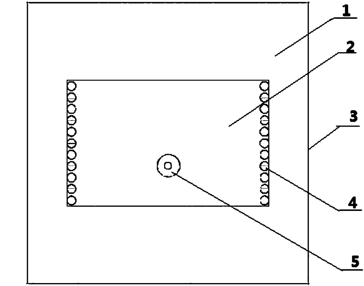
[0025] In the embodiment design made, the size of the dielectric plate of the selected microstrip antenna is 50mm×50mm, the operating center frequency of the microstrip antenna is 10GHz, the size of the rectangular radiation unit is 10.2mm×22.2mm, and the radius of the short-circuit metal cylinder is They are all 0.4mm, 22 in total, and the radius of the feeding probe is 0.3mm. The antenna dielectric plate adopts Rogers Duroid 5880 commercial plate with a dielectric constant of 2.2, a loss tangent of 0.0012, and a thickness of 1.575 mm.

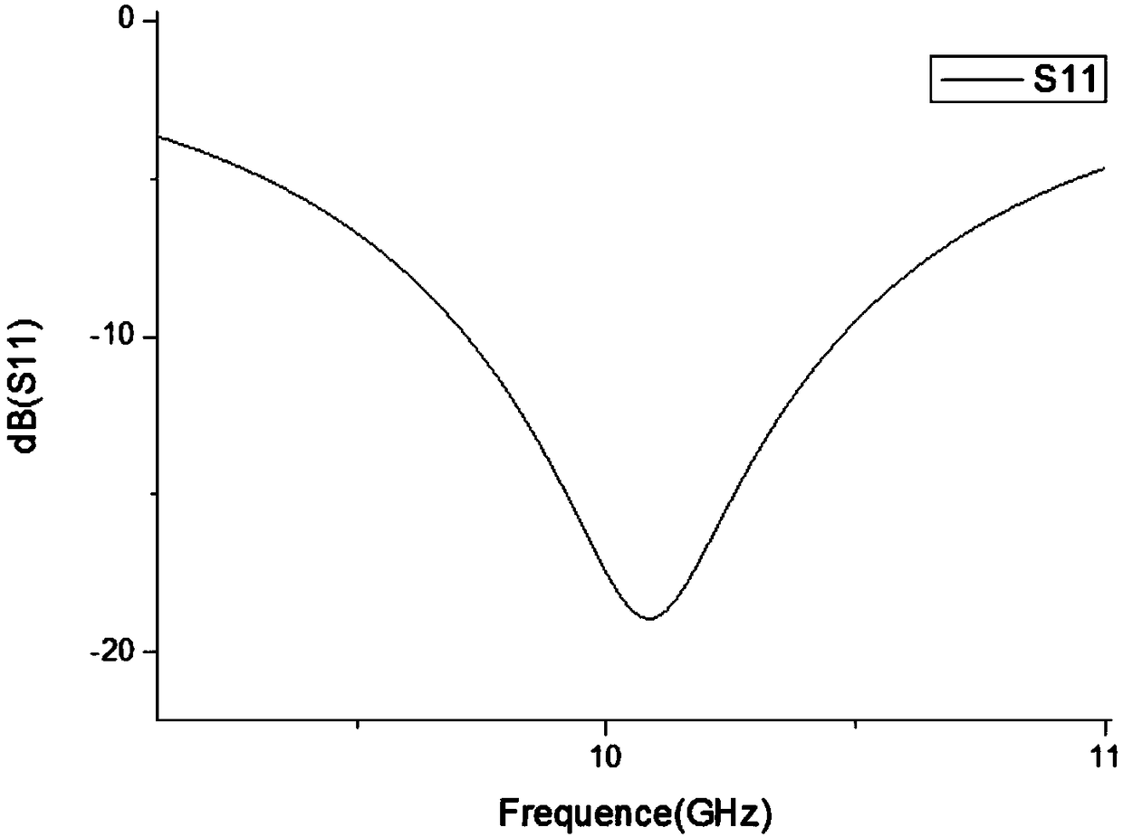
[0026] see figure 2 , is the S11 parameter of a low cross-polarization microstrip patch antenna according to an embodiment of the present invention, and the bandwidth of the antenna covers 9.70-10.50 GHz (8%).

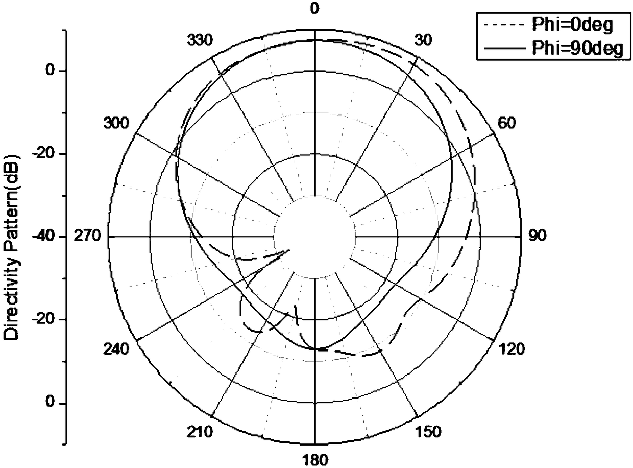
[0027] see image 3 , is the gain diagram of the E and H planes at the center frequency of a low cross-polarized microstrip patch antenna according to an embodiment of the present invention, and the gain reaches 7.4 dB.

[0028] s...


PUM


Abstract

The invention discloses a low cross-polarization microstrip patch antenna, comprising a microwave dielectric substrate, a rectangular metal patch, a metal floor, short-circuited metal pillars and a feeding probe, wherein the rectangular metal patch is disposed on the upper surface of the microwave dielectric substrate, and the metal floor is disposed on the lower surface of the microwave dielectric substrate; two rows of short-circuited metal pillars are arranged on the rectangular metal patch, and are respectively arranged along the edges of two non-radiative sides of the rectangular metal patch, and the short-circuited metal pillars short the rectangular metal patch and the metal floor; and the feeding probe is placed on the rectangular metal patch. The invention realizes excellent low cross polarization, improves the polarization purity of the antenna, increases the gain of the rectangular microstrip patch antenna, and has the advantages of low profile, simple structure, and simpleand convenient processing.

Description

technical field [0001] The invention belongs to the technical field of antennas, in particular to a low cross-polarization microstrip patch antenna. Background technique [0002] With the development of electronic countermeasures technology, phased array radar has become the mainstream of modern radar equipment. In order to effectively deal with severe electronic interference and ARM (anti-radar missile), the method of reducing the antenna sidelobe level and increasing the antenna working bandwidth is usually adopted to improve the anti-jamming performance of phased array radar. The performance of the phased array antenna depends to a large extent on the radiation unit, which requires the design of the antenna unit not only to have broadband characteristics but also to be a low cross-polarization level antenna, otherwise the serious cross-polarization level will be The low or ultra-low sidelobes of the main polarization are rendered meaningless by themselves. [0003] Elec...

Claims


Application Information

Patent Timeline
Patent Type & Authority Applications(China)
IPC IPC(8): H01Q1/38H01Q1/48H01Q1/50H01Q15/24
Inventor 张金栋汤普祥冯敏吴翠翠周雅莉姚祺陈峤羽陈祥云韦一方张弘毅
Owner NANJING UNIV OF SCI & TECH
Why Eureka
Try Eureka