High-gain wideband omnidirectional antenna

An omnidirectional antenna and wide-band technology, which is applied in antennas, slot antennas, antenna arrays, etc., can solve the problems of dual-band wide-band high-gain antennas that cannot meet the requirements, antennas that cannot meet communication requirements, and frequency band control difficulties. The effects of uniform current distribution, no blind area coverage, and easy dual-polarization design

Inactive Publication Date: 2013-04-24
HARBIN ENG UNIV
View PDF5 Cites 4 Cited by
  • Summary
  • Abstract
  • Description
  • Claims
  • Application Information

AI Technical Summary

Problems solved by technology

The main problems of existing antennas are: (1) Most of the existing antennas are dipole antennas and monopole antenna arrays, and the pattern is equal up and down, so a part of the radio wave is consumed, so the gain is relatively low
The current antennas cannot meet the current communication needs, especially the dual-band broadband high-gain antennas cannot meet the requirements
(4) Most of the current cell coverage and beautification antennas use monopole antennas and dipole antennas, and it is difficult to control the frequency band. At the same time, in order to make full use of existing resources and adapt to the needs of different environments, the antenna design is required to be flexible. Can meet the needs of different occasions
Moreover, the products developed are all directional antenna products. Although there are a few broadband omnidirectional antenna products, they are complex in structure, cumbersome in design, poor in versatility, high in processing cost, and have certain defects in performance, so they are not suitable for promotion.
[0003] Literature "Y.Yang, Y.Wang, and A.E.Fathy, Design of compact Vivaldi antenna arraysFor UWB see through wall applications, Progress In Electromagnetics Research, PIER 82, 401-418, 2008", "Zhang Cheng Hao, Wei Hong et al , A novel feeding technique for antipodal linearly tapered Slot Antenna Array, IEEE MTT-S International Microwave Symposium Digest, 2005" etc. are all researching the feeding structure and array structure of the slot antenna, but only from a single feeding or array structure to explain

Method used


Image

  • High-gain wideband omnidirectional antenna
  • High-gain wideband omnidirectional antenna
  • High-gain wideband omnidirectional antenna

Examples


Embodiment 1

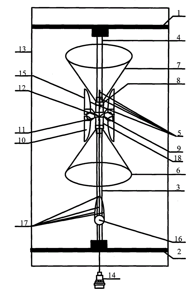
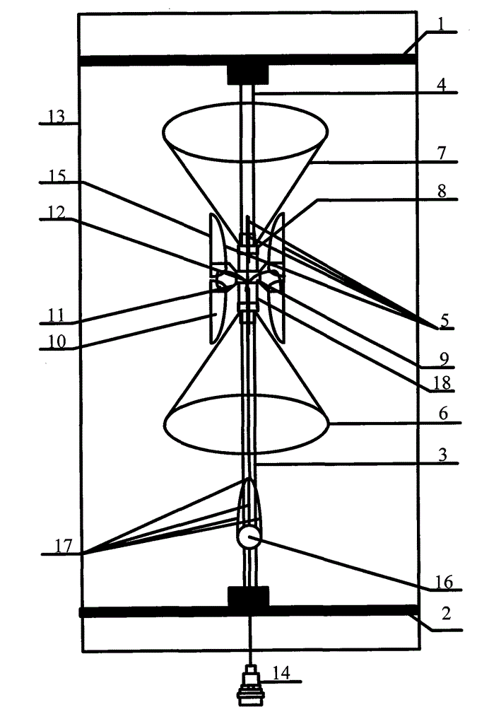
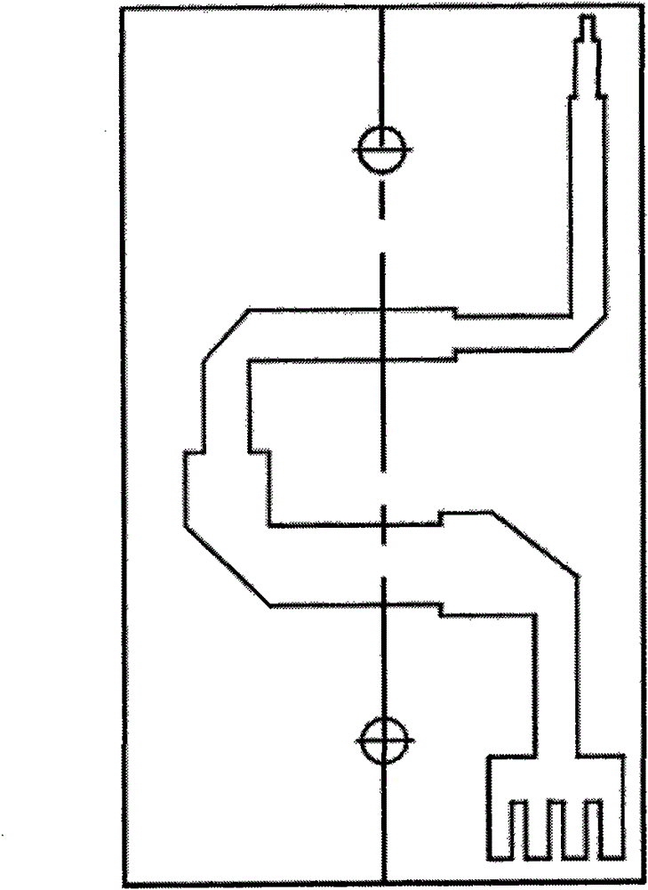
[0018] combine figure 1 and figure 2 , the four slot antennas 5 form a radiation unit, the main feeder cable 14 directly feeds the feeder network 16 through the lower fixed base plate 2, and the feeder network 16 feeds the four slot antennas 5 through the four feeder cables 17 respectively. Electricity. The slot antenna 5 is composed of an upper radiator 15 and a lower radiator 10, and the upper reflector 7 and the lower reflector 6 form a biconical shaped reflector. The slot antenna 5 and the biconical shaped reflector are composed of thinner It is made of copper foil, and the cone angle of the biconical shaped reflector is between 15° and 60°, and both the height of the cone and the cone angle of the biconical shaped reflector can be adjusted. The upper and lower radiators are installed on the PTFE support plate 11 and fixed on the medium pipe 18 through the support cylinder 9 . The slot antenna 5 of the present invention consists of an improved Vivaldi antenna. The wav...

Embodiment 2

[0022] like figure 2 As shown, another embodiment of the present invention is that without changing other components, in order to improve the radiation characteristics of the antenna horizontal plane, that is, to change the uniformity of the radiation on the horizontal plane of the antenna, the slot antenna of the radiating element adopts a parasitic element with a parasitic element. slot antenna. The slot antenna is fed by the feeding cable 17 to the slot antenna 5, wherein 19 is a parasitic element, and the parasitic element is not directly connected with the feeding cable. The antenna designed in this way can not only change the radiation uniformity (out-of-roundness) of the horizontal plane of the antenna, but also guide the propagation of electromagnetic waves to increase the flow path of the current, thereby making it easier to achieve good impedance matching.


PUM


Abstract

The invention provides a high-gain wideband omnidirectional antenna, which comprises a main feeder, a two-cone shaped reflector, a wideband slot antenna, a feed network and an antenna cover. The high-gain wideband omnidirectional antenna has the characteristics of: 1, bandwidth of over 110 percent, higher radiation efficiency, adoption of inconsistent slot line shaped curves and contribution to further widening the bandwidth of the antenna; 2, capacity of being arranged in a plastic bucket and an antenna cover in any shape, ideal directional diagram, capacity of covering the whole space, uniform current distribution, capacities of realizing non-blind area coverage and improving communication quality; 3, capacity of compressing beam width in a vertical plane of the omnidirectional antenna so as to improve the antenna gain due to the adoption of the two-cone shaped reflector structure, capacity of making waves transmitted by a radiating unit radiate from the plane to free space, convenience for improving polarized purity of the antenna; 4, easy implementation of dual-polarized design; and 5, simple technology, fewer welding spots, convenient design and manufacture, and contribution to improving third-order passive intermodulation of the antenna.

Description

(1) Technical field [0001] The present invention relates to an antenna used in the field of mobile communication, in particular to an antenna used in a communication network as an antenna for transmitting and receiving radio signals. (2) Background technology [0002] Radio communication equipment and electronic information equipment are developing in the direction of multi-functionalization, miniaturization, ultra-wideband and friendly coordination with the surrounding environment, which makes broadband, miniaturization and high gain become one of the hot topics of research at home and abroad. The main problems of the existing antennas are: (1) Most of the existing antennas are dipole antennas and monopole antenna arrays, and the directional patterns are equal up and down, so part of the radio waves are consumed, so the gain is relatively low. (2) At present, the antennas used by users are required to be miniaturized, and mobile antennas are required to be well installed in...

Claims


Application Information

Patent Timeline
Patent Type & Authority Patents(China)
IPC IPC(8): H01Q19/18H01Q13/10H01Q1/38H01Q1/42H01Q1/12H01Q21/00
Inventor 杨晓冬李迎松刘乘源吴成云王世刚杨倩王积祥姜兴文李渠塘
Owner HARBIN ENG UNIV
Why Eureka
Try Eureka