
Permanent magnet synchronous motor initial position identification method and device

A technology of permanent magnet synchronous motor and identification method, which is applied in the direction of control of electromechanical transmission, control of generator, motor generator control, etc. It can solve the problems of motor runaway, reduce motor output torque, and endanger the personal safety of operators. Achieve the effect of avoiding out-of-control speeding, improving reliability and ensuring smooth start

Inactive Publication Date: 2018-11-23
HUAZHONG UNIV OF SCI & TECH
View PDF3 Cites 5 Cited by
  • Summary
  • Abstract
  • Description
  • Claims
  • Application Information

AI Technical Summary

Problems solved by technology

The closed-loop vector control of the permanent magnet synchronous motor must first determine the initial position of the motor rotor. The accuracy of the determination of the initial rotor position is related to whether the motor can run normally. If the initial position of the rotor is detected incorrectly, the motor will run out of control, endangering the personal safety of the operator Even if there is a certain error in the initial position of the rotor, the output torque of the motor will be reduced, which will affect the operating efficiency of the motor. The motor will heat up seriously, and the driver will alarm for overcurrent or overload.

Method used


Image

  • Permanent magnet synchronous motor initial position identification method and device
  • Permanent magnet synchronous motor initial position identification method and device
  • Permanent magnet synchronous motor initial position identification method and device

Examples


Embodiment Construction

[0030] In order to have a clearer understanding of the technical features, purposes and effects of the present invention, the specific implementation manners of the present invention will now be described in detail with reference to the accompanying drawings.

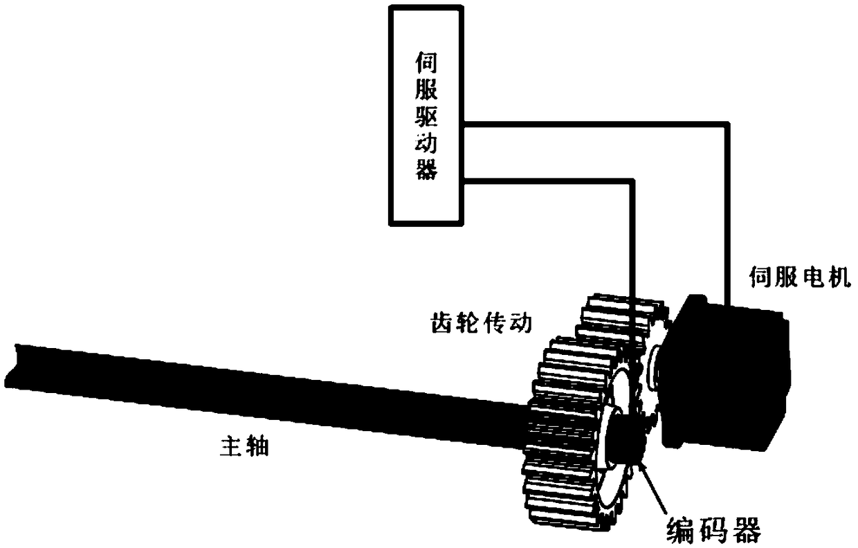
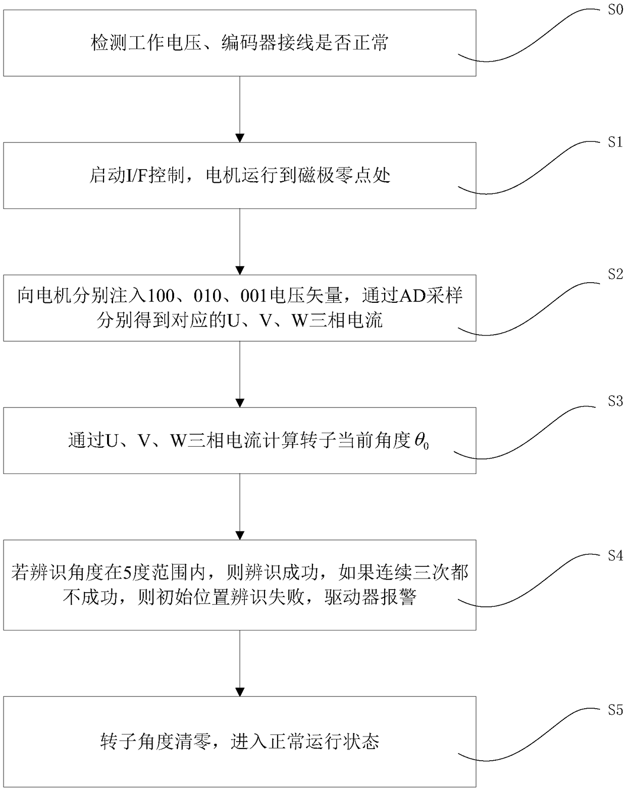
[0031] Such as figure 1 As shown, it is the application range of the present invention, that is, the background condition. The encoder is installed on the main shaft of the machine, and the motor has no space to install the encoder due to the installation size requirements. Due to the problem of mechanical gear ratio, the positions of the encoder and the rotor of the motor are not one by one. Therefore, the initial position of the rotor must be automatically identified after the drive is powered on. figure 2 The flow chart of the initial position identification method is given. Include the following steps:

[0032] S0: When the system is powered on, the servo driver checks whether the working voltage and encoder wiri...


PUM


Abstract

The invention discloses a permanent magnet synchronous motor initial position identification method and device. The permanent magnet synchronous motor initial position identification method comprisesthe following steps that first I / f open-loop operates and pulls a permanent magnet synchronous motor rotor to a zero point, then 100, 010 and 001 voltage vectors are injected into the motor, and a UVWthree-phase current is sampled through AD; and a current position of the rotor is calculated according to the three-phase current, if the current position is near the zero point, the identification is successful and the motor enters a normal operation state, and the purpose of injecting the voltage vectors is to further confirm whether the rotor position is at the zero point or not. And therefore, the permanent magnet synchronous motor initial position identification method can accurately identify the initial position of the rotor, ensures the smooth start and normal operation of the permanent magnet synchronous motor, avoids the problems of getting out of control and galloping during the start and overflowing and overloading during operation, and improves the reliability of an alternating current servo drive system.

Description

technical field [0001] The invention relates to the technical field of servo drive control, and more specifically, to a method and device for identifying an initial position of a permanent magnet synchronous motor. Background technique [0002] The permanent magnet synchronous motor has the advantages of small size, high power density and high reliability, and has a relatively high proportion in today's AC servo control system. Servo systems for permanent magnet synchronous motors are mostly closed-loop control systems, and position sensors need to be installed to obtain real-time position information and speed information of the rotor. However, in some practical applications, position sensors cannot be installed due to environmental influences. Therefore, sometimes the position sensor is installed outside the motor, such as on the machine shaft, but due to a certain mechanical transmission ratio, the motor rotor angle and the output of the position sensor are not in a one-t...

Claims


Application Information

Patent Timeline
IPC IPC(8): H02P21/32H02P21/18H02P27/12
Inventor 李海春尹泉罗慧刘洋
Owner HUAZHONG UNIV OF SCI & TECH
Learn More