Device priority control system

A control system and priority technology, applied in the direction of electrical components, pulse technology, electronic switches, etc., can solve the problems of unfavorable nuclear power plant economy, expensive safety level controllers, and inferior reliability to relays, etc., to achieve low cost and high cost , the effect of high inherent reliability

Active Publication Date: 2018-11-23
CHINA NUCLEAR POWER TECH RES INST CO LTD +2
View PDF5 Cites 1 Cited by
  • Summary
  • Abstract
  • Description
  • Claims
  • Application Information

AI Technical Summary

Problems solved by technology

The implementation of priority control requires the use of controllers, which are not as reliable as relays, and the safety-level controllers used in nuclear power plant systems are very expensive, which is not conducive to the economics of nuclear power plants

Method used


Image

  • Device priority control system
  • Device priority control system

Examples


Embodiment Construction

[0025] In the following description, specific details such as specific system structures and technologies are presented for illustration rather than limitation, so as to thoroughly understand the embodiments of the present invention. It will be apparent, however, to one skilled in the art that the present invention may be practiced in other embodiments without these specific details. In other instances, detailed descriptions of well-known systems, devices, circuits, and methods are omitted so as not to obscure the description of the present invention with unnecessary detail.

[0026] In order to illustrate the technical solutions described in the present invention, the following description will be made through specific implementation methods in conjunction with the accompanying drawings.

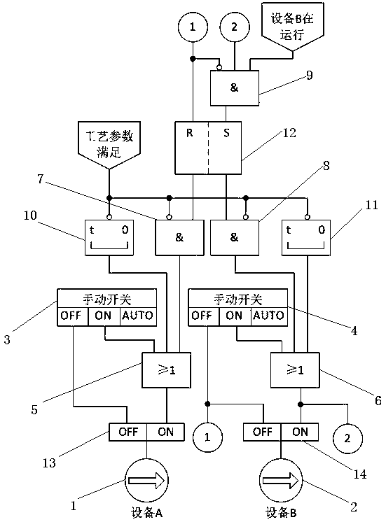
[0027] Such as figure 1 Shown is a schematic circuit diagram of a device priority control system provided by an embodiment of the present invention, wherein the system includes a device A1...


PUM


Abstract

The invention discloses a device priority control system. The system comprises a device A and a device B, which have the same function, wherein the device A and the device B are connected in parallel;and the system further comprises a first switch module, a second switch module, a first OR gate circuit, a second OR gate circuit, a first AND gate circuit, a second AND gate circuit, a third AND gate circuit, a first time relay, a second time relay, and an RS flip-flop. The system of the invention realizes the priority control of two columns of devices that are connected in parallel and have thesame function in a nuclear power plant system through the relays, the components and parts are simple, and the inherent reliability is high; the device priority control of the system requires no controller, so that the implementation cost is low; a standby device can be automatically put into operation when the running device is faulty or when the system process parameters are not met; and the system logic design is smart, the implementation of the device priority does not affect the test requirements of the devices, and the devices having the same function do not interfere with each other during the test.

Description

technical field [0001] The invention relates to the technical field of equipment control, in particular to an equipment priority control system. Background technique [0002] The nuclear power plant system is often equipped with two parallel devices with the same function, and adopts the operation mode of one in use and one in standby, that is, during normal operation, one of the devices is put into operation and the other is in standby. When the operating equipment cannot meet the requirements of the system process parameters or fails, the standby equipment will be put into operation. [0003] The existing technology adopts the following methods to switch and put into operation the backup equipment: [0004] 1) Use manual switching to control parallel-connected equipment with the same function in the system, that is, manually select one equipment to start first, and when the system process parameters do not meet the requirements, manually put into operation the standby equ...

Claims


Application Information

Patent Timeline
Patent Type & Authority Applications(China)
IPC IPC(8): H03K17/00
CPCH03K17/002
Inventor 杨杰伟李剑波张伟周舟王利翁文庆杨俊钙孙江枫
Owner CHINA NUCLEAR POWER TECH RES INST CO LTD
Why Eureka
Try Eureka