Supercharge Your Innovation With Domain-Expert AI Agents!

Air conditioner and its control method

An air-conditioning and air technology, applied in the direction of air-conditioning systems, refrigerators, heating methods, etc., can solve the problems of complex pipeline structure, complex composition, and large number of outlets, so as to prevent heat loss, prevent bacterial reproduction, and improve humidity adjustment capabilities Effect

Active Publication Date: 2021-10-08
KYUNGDONG NAVIEN
View PDF8 Cites 0 Cited by
  • Summary
  • Abstract
  • Description
  • Claims
  • Application Information

AI Technical Summary

Problems solved by technology

[0009] However, the above-mentioned prior art has the following problems: it is necessary to match two outlets 14 for discharging air to the outside, and two outlets 13a, 13b for discharging air indoors, so the number of outlets is large, and the structure of the pipeline connected thereto is complicated.
In addition, since the two discharge ports 13a, 13b each drive a separate opening and closing plate, there is a problem that the configuration is complicated.

Method used


Image

  • Air conditioner and its control method
  • Air conditioner and its control method
  • Air conditioner and its control method

Examples


no. 1 example

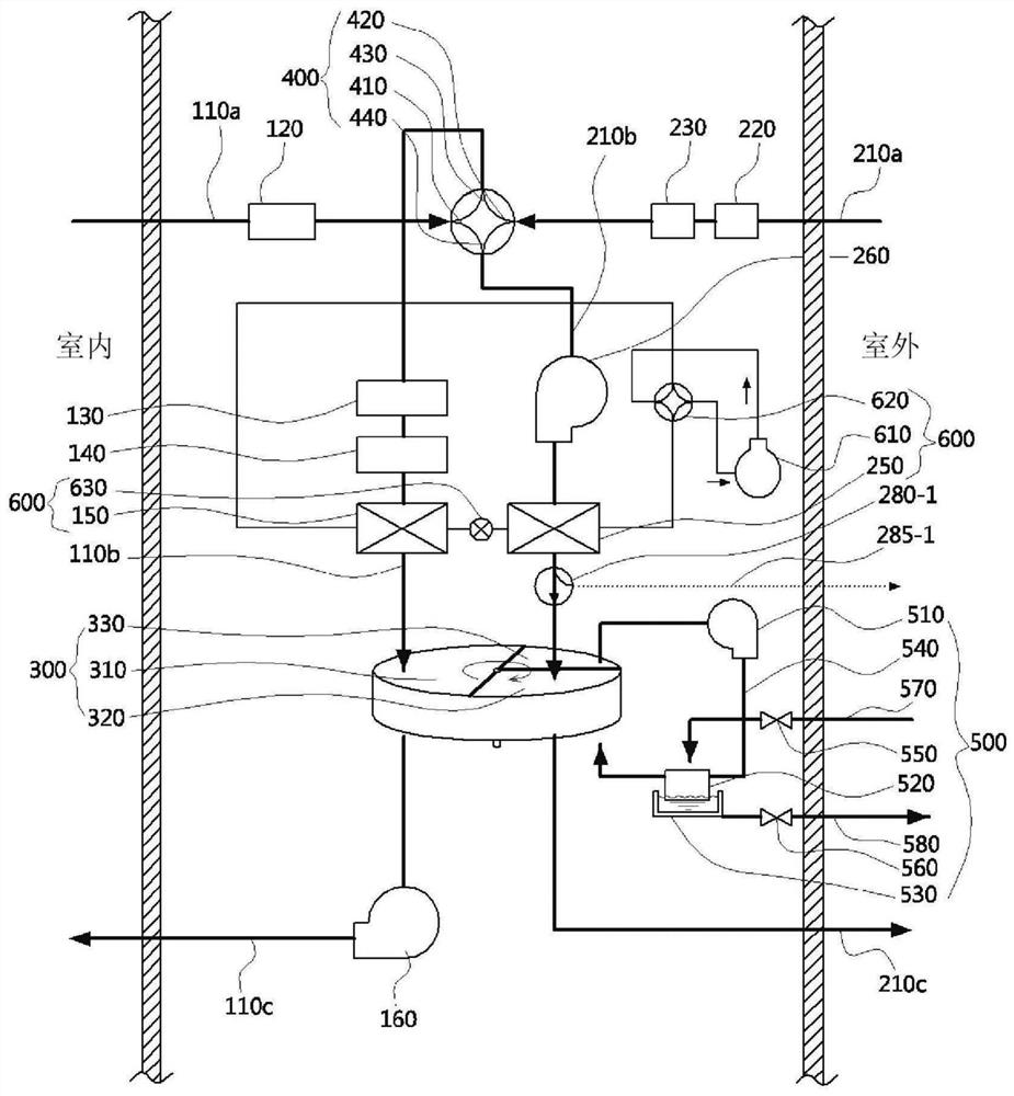
[0084] refer to figure 1 The configuration of the air conditioner according to the first embodiment of the present invention will be described.

[0085] The air conditioner of the first embodiment includes: a first air flow path 110, both ends of which are connected to the room; a second air flow path 210, whose two ends are connected to the outside; The first area 310 of the first area 310, the second area 320 equipped on the second air flow path 210, and the adsorbent that alternately passes through the first area 310 and the second area 320 by rotation; the heat pump 600 makes the first heat The exchanger 150 and the second heat exchanger 250 alternately function as a condenser and an evaporator, thereby heating and cooling the air flowing in the first air passage 110; a controller (not shown) controls the The rotation of the rotor part 300 and the heat pump 600 are described.

[0086] The first air flow path 110 includes: an inlet portion 110a for allowing indoor air on ...

no. 2 example

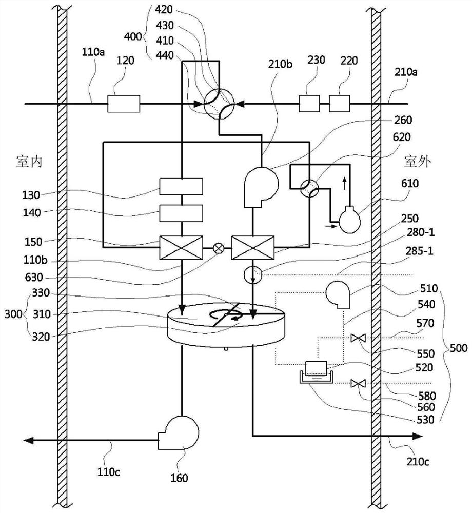
[0161] refer to Figure 8 The configuration of an air conditioner according to a second embodiment of the present invention will be described.

[0162] The difference between the air conditioner of the second embodiment and the first embodiment is that it includes a third heat exchanger 170, a fourth heat exchanger 270, and a heat pump 600 equipped with a first expansion valve 630-1 and a second expansion valve 630-2, In addition, the positions of the damper 280-2, the bypass flow path 285-2, and the second air blower 260 are different, and the rest of the configuration is the same.

[0163] The third heat exchanger 170 is disposed between the first area 310 and the first blower 160 to exchange heat with the air passing through the first area 310 . The fourth heat exchanger is disposed between the second area 320 and the second air blower 260 to exchange heat with the air passing through the second area 320 .

[0164] The refrigerant supplied from the compressor 610 circulat...


PUM


Abstract

The object of the present invention is to provide an air conditioner and its control method capable of realizing humidity adjustment, cooling, heating, air purification and ventilation with a simple structure. The present invention for achieving this purpose includes: a first air flow path, both ends of which are connected to the room; a second air flow path, both ends of which are connected to the outside; area, a second area provided on the second air flow path, and an adsorbent that alternately passes through the first area and the second area by rotation; a heat pump including heat exchange with air flowing toward the first area a first heat exchanger and a second heat exchanger for heat exchange with the air flowing to the second zone, and the first heat exchanger and the second heat exchanger are operated alternately as condensers and evaporators a device for heating and cooling the air flowing in the first air passage; and a control unit for controlling the rotation of the rotor member and the heat pump.

Description

technical field [0001] The present invention relates to an air conditioner and a control method thereof, in particular to an air conditioner capable of operating a humidity adjustment mode, a cooling / heating mode, an air purification mode and a ventilation mode and a control method thereof. Background technique [0002] Generally, an air conditioner is a device that adjusts indoor temperature and humidity according to user needs, or ventilates indoor air to maintain indoor comfort. [0003] Recently, technologies are being developed that can maintain indoor air in a comfortable state in accordance with seasonal changes according to user selections by adding various functions such as dehumidification, humidification, cooling, heating, air purification, and ventilation to air conditioners. [0004] Such air conditioners include humidifiers that increase the humidity of indoor air and dehumidifiers that lower the humidity of indoor air. Moreover, the indoor cooling / heating fun...

Claims


Application Information

Patent Timeline
Patent Type & Authority Patents(China)
IPC IPC(8): F24F11/89F25B29/00F25B49/02F25B41/20F25B39/02F25B39/04F25B41/31F24F8/117F24F8/10F24F12/00F24F6/02
CPCY02B30/70
Inventor 李东根李基成梁承大
Owner KYUNGDONG NAVIEN
Features
  • R&D
  • Intellectual Property
  • Life Sciences
  • Materials
  • Tech Scout
  • Unparalleled Data Quality
  • Higher Quality Content
  • 60% Fewer Hallucinations
Learn More