Wavelength conversion member, manufacturing method therefor, and light-emitting device

A technology of wavelength conversion and manufacturing method, which is applied in the direction of luminescent materials, lighting devices, luminescent coatings, etc., can solve the problem of not clearly describing the detailed structure of the abutment part of the fluorescent layer and the radiator abutment method, and achieve the suppression of thermal quenching, The effect of efficient heat dissipation

Active Publication Date: 2018-11-23
NGK SPARK PLUG CO LTD
View PDF16 Cites 3 Cited by
  • Summary
  • Abstract
  • Description
  • Claims
  • Application Information

AI Technical Summary

Problems solved by technology

However, Patent Document 7 does not clearly describe the detailed structure of the a

Method used


Image

  • Wavelength conversion member, manufacturing method therefor, and light-emitting device
  • Wavelength conversion member, manufacturing method therefor, and light-emitting device
  • Wavelength conversion member, manufacturing method therefor, and light-emitting device

Examples


Embodiment

[0073] (1. Evaluation of joining state)

[0074] (1-1) Preparation method of the sample

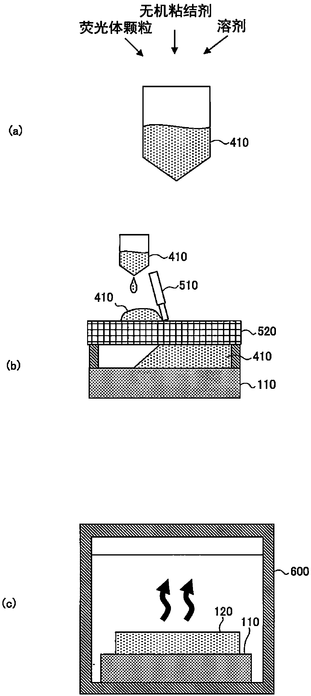
[0075] The wavelength conversion members of Example 1, Comparative Examples 1 and 2 were fabricated. First, ethyl silicate, terpineol, and YAG phosphor particles (average particle diameter: 18 μm) were mixed to prepare a paste.

[0076] The prepared paste was applied on a sapphire plate serving as a transmissive material to a thickness of 40 μm using a screen printing method, followed by heat treatment to obtain an intermediate member. SEM observation was performed on a cross section perpendicular to the reflecting surface of the obtained intermediate member. Figure 4 (a) is a SEM photograph showing a partial cross section of a wavelength conversion member (cross section of an intermediate member). in addition, Figure 4 (b) is Figure 4 Si element mapping image of a partial cross-section of the wavelength conversion member shown in the SEM photograph of (a). It was confirmed that ...


PUM


Abstract

Provided are: a wavelength conversion member capable of efficiently dissipating heat from a site that tends to generate heat when irradiated with light having a high energy density, thereby minimizingthe thermal quenching of phosphor; a manufacturing method for the wavelength conversion member; and a light-emitting device. The reflective-type wavelength conversion member 100, which converts lighthaving a wavelength within a specific range to light of another wavelength while reflecting light from the reflection surface for use as illumination light, comprises: a transmissive material 110 comprising an inorganic material and transmitting light; a phosphor layer 120 bonded to the transmissive material 110 and comprising phosphor particles that emit converted light in response to the absorbed light and a translucent ceramic that couples the phosphor particles together; and a reflection material 130 disposed on the opposite side of the transmissive material 110 and in contact with the phosphor layer 120 with the surface serving as a reflection surface for the converted light. Thus, it is possible to efficiently dissipate heat from the site which tends to generate heat when irradiatedwith light having a high energy density, thereby minimizing the thermal quenching of the phosphor.

Description

technical field [0001] The present invention relates to a reflective wavelength conversion member that converts light of a specific range of wavelengths into light of other wavelengths and forms irradiated light by reflecting the light on a reflective surface, its manufacturing method, and a light emitting device. Background technique [0002] As a light-emitting element, there is known a light-emitting element in which a wavelength conversion member in which phosphor particles are dispersed in a resin typified by epoxy resin or silicone resin is disposed so as to contact a blue LED element. Furthermore, in recent years, instead of LEDs, laser diodes (LDs), which have high energy efficiency and are easy to cope with miniaturization and high output, have been increasingly used. [0003] Since the laser beam is locally irradiated with high-energy light, the irradiated portion of the resin that is intensively irradiated with the laser beam is scorched. In this regard, it is kn...

Claims


Application Information

Patent Timeline
IPC IPC(8): G02B5/20C09K11/08H01L33/50
CPCC09K11/08G02B5/20H01L33/50C09K11/7706C09D5/22H01L33/10H01L33/44H01L33/502F21V29/70F21Y2115/30F21K9/64F21Y2115/10F21V9/32F21V13/08
Inventor 佐藤友美传井美史阿部誉史佐藤豊
Owner NGK SPARK PLUG CO LTD
Why Eureka
Try Eureka