Automatic profile steel production line

A technology of production line and section steel, which is applied in the field of section steel processing, can solve the problems of high labor intensity of operators, backward construction technology, and easy injury of workers, etc., to improve straightening effect, facilitate orderly discharge, and improve safety Effect

Inactive Publication Date: 2018-11-27
扬州八方冷拉型钢有限公司
View PDF0 Cites 3 Cited by
  • Summary
  • Abstract
  • Description
  • Claims
  • Application Information

AI Technical Summary

Problems solved by technology

At present, domestic cold-drawing production is usually carried out in the form of an assembly line composed of a single equipment according to the processing process. After each equipment completes a process, it is sent to the next process for the next process by manually equipped with some handling equipment. Processing, this kind of construction technology is backward, the production efficiency is low, and the labor intensity of the operators is relatively high. Therefore, an automated production line has appeared in the existing technology, which does not require manual handling and improves production efficiency. However, the following problems still exist. In the ordinary production line The steel wire rods are all directly stacked and placed, and the wire rods are sent to the cooling production line for processing through tension. When the tension is too large, the directly stacked wire rods are easy to fall over. Due to the heavy weight of the steel wire rods, it is particularly easy to Injure staff, low safety factor

Method used


Image

  • Automatic profile steel production line
  • Automatic profile steel production line
  • Automatic profile steel production line

Examples


Embodiment Construction

[0021] Below in conjunction with specific embodiment, further illustrate the present invention, it should be understood that these embodiments are only used to illustrate the present invention and are not intended to limit the scope of the present invention, after reading the present invention, those skilled in the art will understand the various equivalent forms of the present invention All modifications fall within the scope defined by the appended claims of the present application.

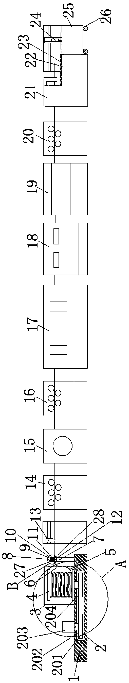
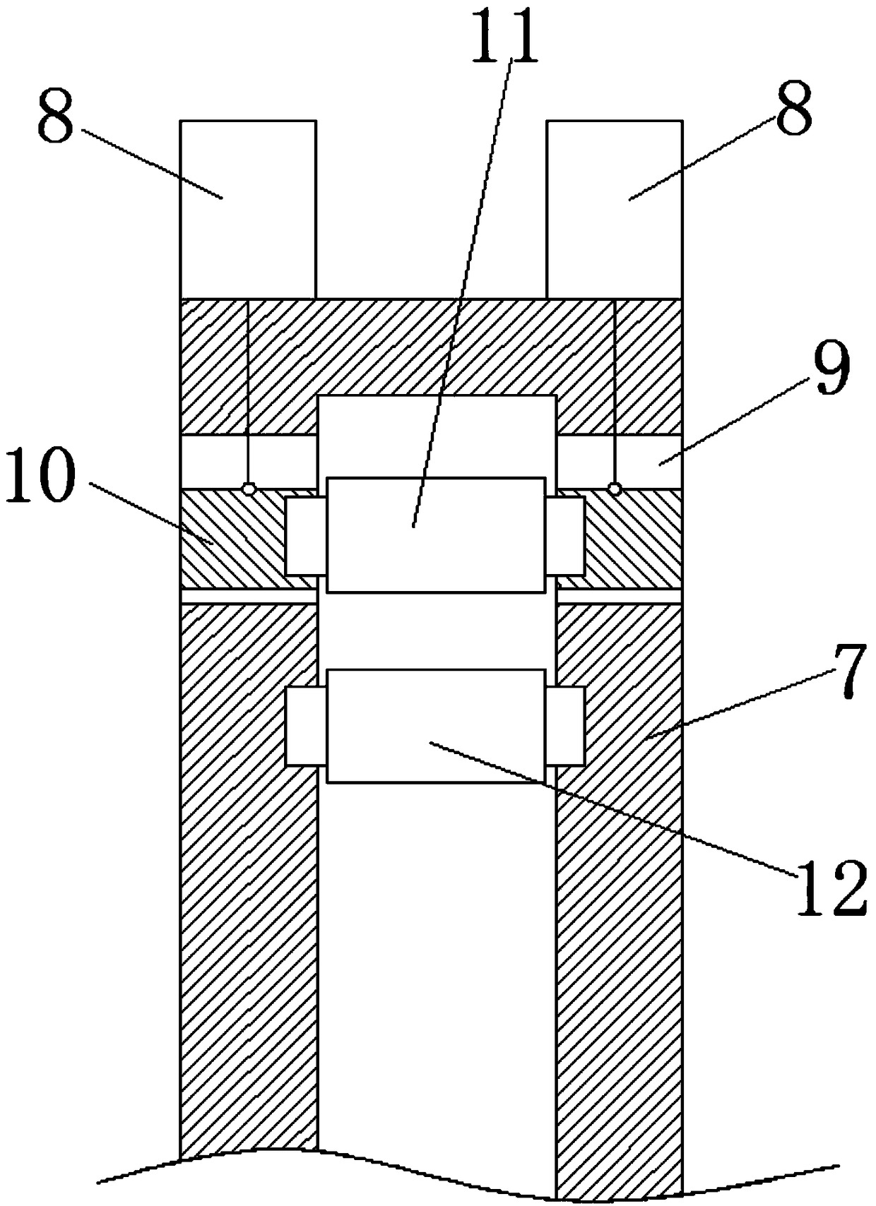
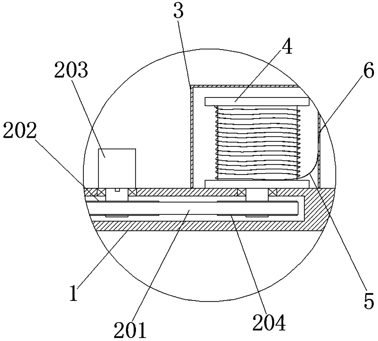
[0022] Such as Figure 1-4 As shown, an automated section steel production line includes a feeding device arranged in sequence along the moving direction, a pre-leveler 14, a sand blasting descaling machine 15, a first fine straightening machine 16, a steel brush descaling machine 17, and a cold drawing machine 18. Profile steel grinding machine 19, second fine straightening machine 20, profile steel cutting machine 21, discharge device, the feed device includes a base 1, and also includes a tu...


PUM


Abstract

The invention discloses an automatic profile steel production line in the technical field of profile steel machining. The automatic profile steel production line comprises a feeding device, a pre-straightening machine, a sandblast derusting machine, a first fine straightening machine, a steel brush derusting machine, a cold drawing machine, a profile steel polishing machine, a second fine straightening machine, a profile steel cutting machine and a discharging device, wherein the feeding device comprises a base, a rotating disc and a first mechanical arm, the rotating disc is rotatably mountedon the base and is used for reeling steel bars, and the first mechanical arm is used for dragging the steel bars to the pre-straightening machine; the rotating disc is provided with a driving assembly for driving the rotating disc to rotate, a guiding assembly for guiding the steel bars is arranged on one side, close to the rotation disc, of the base and comprises a bracket, the bracket is arranged on the base, an upper guiding wheel and a lower guiding wheel are mounted on the bracket, the lower guiding wheel is rotatably mounted on the bracket, and a first gap convenient for the steel barsto pass through is formed between the upper guiding wheel and the lower guiding wheel. The automatic profile steel production line has the advantages that the paying off of the steel bars is facilitated, the materials are conveniently conveyed, and meanwhile, the safety is improved.

Description

technical field [0001] The invention relates to the technical field of section steel processing, in particular to an automatic section steel production line. Background technique [0002] Cold-drawn steel is a steel of various cross-sectional shapes and sizes processed by cold-drawing. Cold-drawn processing refers to passing the metal wire rod through the cavity mold under normal temperature conditions. Under the action of strong tension and speed, Force the wire rod to be pulled out of the cavity mold to obtain the required shape, size and extruded parts with certain mechanical properties. It is often used for parts with complex cross-sectional shapes, high precision requirements, and high surface roughness requirements. billet. Cold-drawn steel can be used as a complete set for the automobile industry, hardware tool industry, machinery processing manufacturing industry, and textile machinery processing manufacturers. Diesel engines, musical instruments, household applian...

Claims


Application Information

Patent Timeline
IPC IPC(8): B21C37/04B21C19/00B21C43/02B21C47/18
CPCB21C37/04B21C19/00B21C43/02B21C47/18
Inventor 黄干龙
Owner 扬州八方冷拉型钢有限公司
Why Eureka
Try Eureka