A tooth-shaped multi-pole T-connection projection welding method for cable trays

A cable tray, multi-pole technology, applied in the field of resistance projection welding, can solve the problems of unstable quality, large deformation, large energy consumption, etc., and achieve the effects of reducing production costs, improving product quality, and reducing energy consumption

Active Publication Date: 2020-06-02
JIANGSU ONEQ ELECTRICAL APPLIANCE GRP
View PDF6 Cites 0 Cited by
  • Summary
  • Abstract
  • Description
  • Claims
  • Application Information

AI Technical Summary

Problems solved by technology

[0003] Purpose of the invention: The purpose of the present invention is to provide a tooth-shaped multi-pole T-type connection projection welding method for cable trays, which can solve the problems of low efficiency and energy consumption in the T-type connection welding process in the production of high-strength topology thin-plate bridges. Large size, low precision, large deformation, unstable quality, affecting appearance and other problems; solve the problem that when the material is selected from the anti-corrosion hot-dip galvanized steel plate and stainless steel plate, the gas shielded welding will damage the anti-corrosion performance of the weld and affect the quality of the product and the overall appearance, so that the bridge products meet the requirements of high-quality social development

Method used


Image

  • A tooth-shaped multi-pole T-connection projection welding method for cable trays
  • A tooth-shaped multi-pole T-connection projection welding method for cable trays
  • A tooth-shaped multi-pole T-connection projection welding method for cable trays

Examples


Embodiment Construction

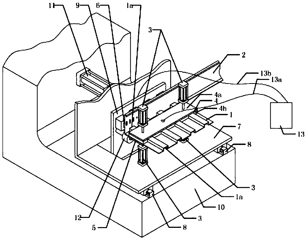
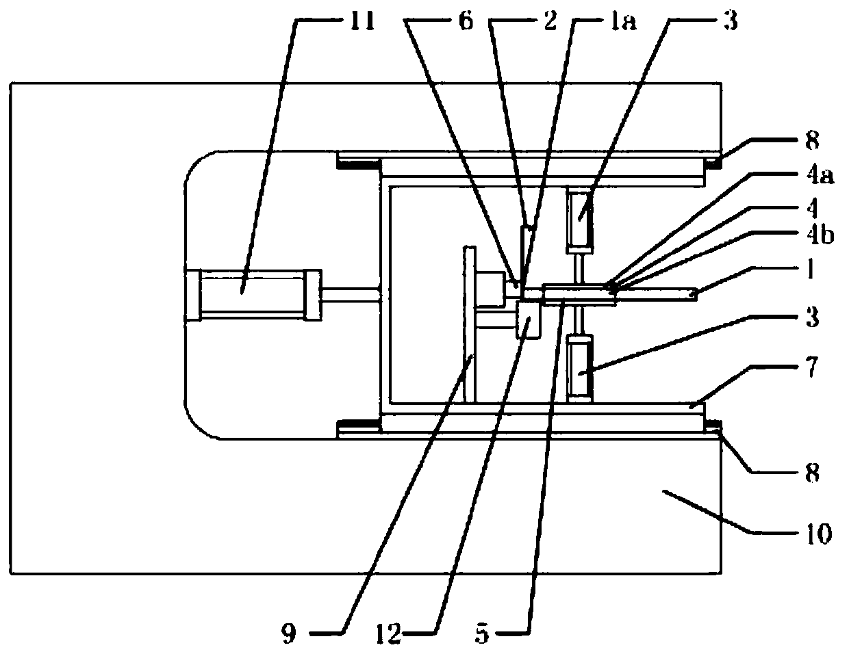
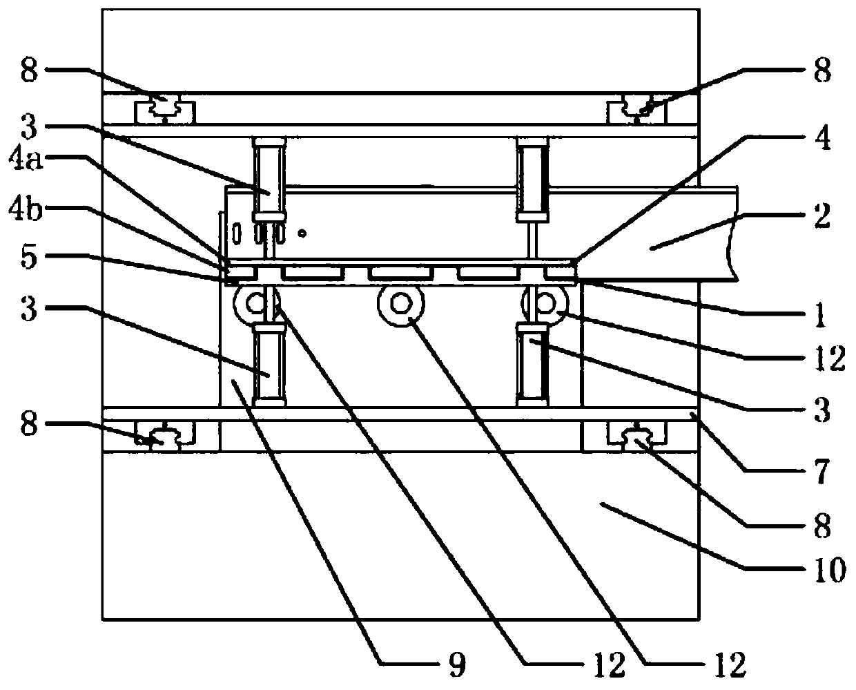
[0030] The cable tray is composed of the bottom plate 1 of the tray, the left side panel 2 of the tray, and the right side panel 14 of the tray. The plates 14 are welded separately. The base plate tooth pole 1a is made at the end part of the bridge base plate 1, and the size, shape and quantity of the tooth shape are set according to the needs of the product.

[0031] The tooth-shaped pole of the bottom plate is composed of a plurality of continuous convex points.

[0032] The tooth-shaped pole of the bottom plate is composed of a plurality of discontinuous convex points.

[0033] The tooth-shaped pole of the bottom plate has a convex point in a triangle or a semicircle.

[0034] The left side plate of the bridge frame and the right side plate of the bridge frame are provided with a plurality of convex points on the lower side of the side plate corresponding to the position of the bottom plate of the bridge frame to be welded to form the side plate convex points.

[0035] F...


PUM


Abstract

The invention relates to a toothed multi-pole T-type connection protrusion welding method for a cable bridge, the method comprises the following steps of: making the end part of the workpiece connected with the end face into a tooth shape, When welding, the tooth shape of the end of the workpiece is used as a bump, the workpiece with the bump is clamped up and down by the jig, the alignment of theplanar workpiece and the bump workpiece is clamped by the jig, the clamps of the two parts of the workpieces are provided with conductive blocks, and the conductive blocks and the T-shaped connectedwelded workpiece are closely fitted to form the current channel needed for welding; At least a plurality of weld stations can be arrange along that length direction of the cable tray for simultaneouswelding, When welding, the workpiece with toothed bump compresses the welded part of the planar workpiece, and the electric current is inputted at the same time. Under the action of large electric current, because the toothed bump conductive contact surface is small, the resistance increases instantaneously, and the overheating reaction occurs at the contact area between the workpiece bump and theplanar surface to form a dot-shaped continuous welding surface.

Description

technical field [0001] The invention relates to a multi-pole resistance welding projection welding method for T-shaped connection used in the manufacture of cable trays, and belongs to the technical field of resistance projection welding. Background technique [0002] Since the bottom plate of the light-duty reinforced tray-type cable bridge adopts a concave-convex corrugated structure, the bottom plate and the side plate need to be produced separately and then assembled into a whole. When the side plate and the bottom plate are assembled, the end face of the bottom plate must be connected with the side plate plane. T-shaped connection, At present, the welding forming process used for the T-connection assembly of the bottom plate and the side plate of the cable tray is gas shielded welding. The filler wire is melted and welded by pulse short circuit. Since the cable tray is made of thin plate, this welding method often causes unstable arc starting. It is easy to cause leakag...

Claims


Application Information

Patent Timeline
Patent Type & Authority Patents(China)
IPC IPC(8): B23K11/14
CPCB23K11/14
Inventor 马纪财马松涛
Owner JIANGSU ONEQ ELECTRICAL APPLIANCE GRP
Why Eureka
Try Eureka