Stamping mechanical equipment for processing optical instrument component

A technology of optical instruments and mechanical equipment, which is applied in the field of optical instrument parts processing, can solve the problems of easily scratched hands, clothing, parts quality impact, and easy to leave a lot of burrs, so as to facilitate pick-and-place operations, improve quality, and prevent The effect of dislocation

Inactive Publication Date: 2018-11-27
江苏鸿鹄激光科技有限公司
View PDF0 Cites 2 Cited by
  • Summary
  • Abstract
  • Description
  • Claims
  • Application Information

AI Technical Summary

Problems solved by technology

[0002] Optical instruments are a very important component category in the instrumentation industry, and are indispensable tools for observation, testing, analysis, control, recording and transmission in various fields of industrial and agricultural production, resource exploration, space exploration, scientific experiments, national defense construction and social life , when manufacturing instrument parts, the parts need to be cut in order to meet the size requirements of the parts. Since the cutting knife and the parts are cut hard, it is easy to leave a lot of burrs on the cutting surface and corners. When picking and placing the finished product , it is very easy to scratch hands, clothes, etc., and it also affects the quality of parts. Therefore, we propose a stamping-type mechanical equipment for processing optical instrument parts

Method used


Image

  • Stamping mechanical equipment for processing optical instrument component
  • Stamping mechanical equipment for processing optical instrument component
  • Stamping mechanical equipment for processing optical instrument component

Examples


Embodiment Construction

[0016] The following will clearly and completely describe the technical solutions in the embodiments of the present invention with reference to the accompanying drawings in the embodiments of the present invention. Obviously, the described embodiments are only some, not all, embodiments of the present invention. Based on the embodiments of the present invention, all other embodiments obtained by persons of ordinary skill in the art without making creative efforts belong to the protection scope of the present invention.

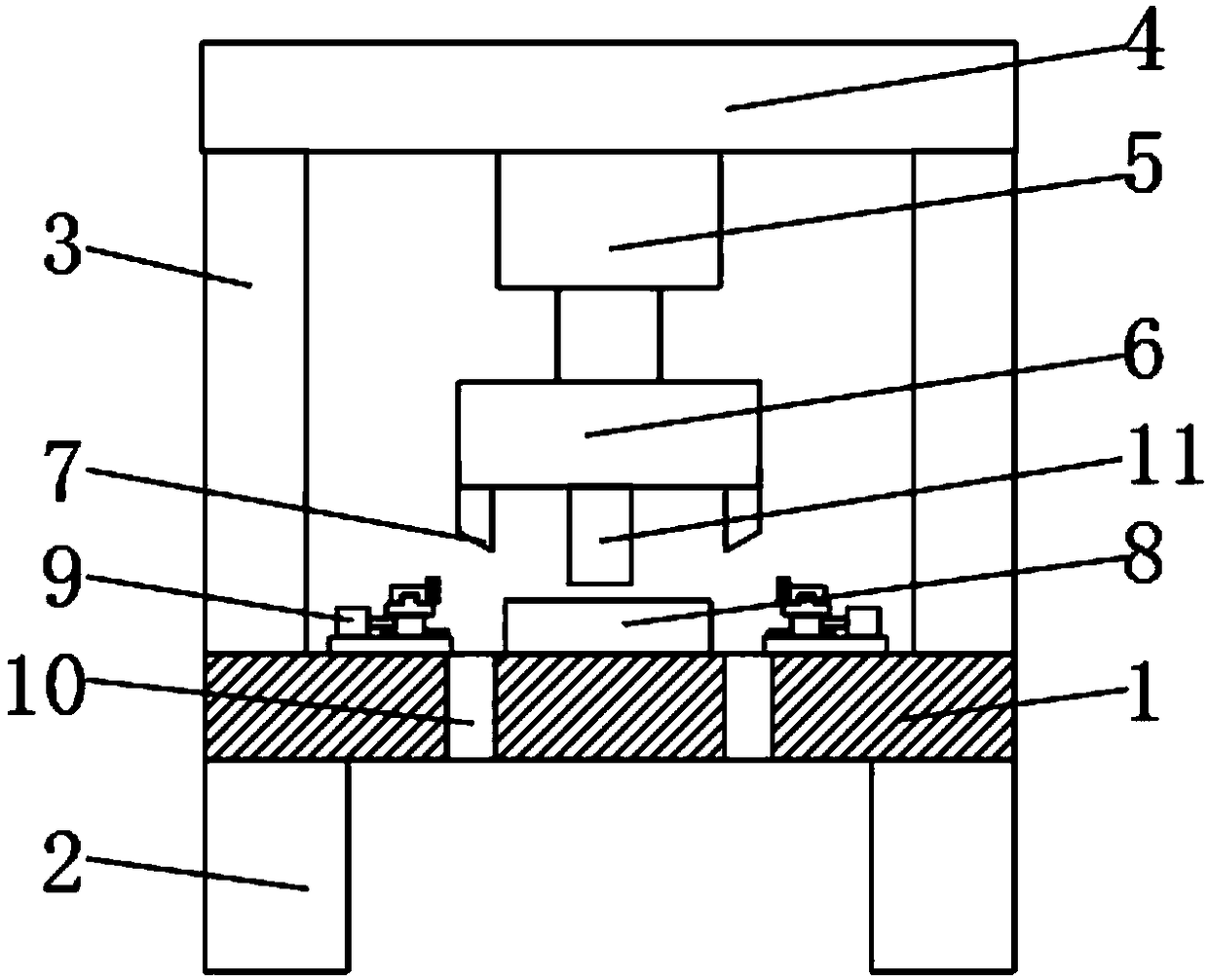
[0017] see Figure 1-4 , the present invention provides a technical solution: a stamping-type mechanical equipment for processing optical instrument parts, including a base 1, the left and right sides of the bottom of the base 1 are fixed with supporting feet 2, and the top, left and right sides of the base 1 are fixed There are support columns 3, and a top plate 4 is fixed on the top of two groups of support columns 3, and a first electric telescopic rod 5 is...


PUM


Abstract

The invention belongs to the technical field of processing optical instrument components and discloses stamping mechanical equipment for processing the optical instrument components. The stamping mechanical equipment for processing the optical instrument components is characterized in that a top plate is fixed on top of two sets of support columns; a first electric telescopic rod is fixed in the middle of the bottom of the top plate; a cutter head is connected to the bottom of the first electric telescopic rod; both sides of the left and right of the bottom of the cutter head are fixedly provided with cutting tools; a pressing device is fixed in the middle of the bottom of the cutter head; a workbench is fixed in the middle of the top of a base; the top of the base is opened with two setsof cutter grooves which are of the same structure and cooperate with the cutting tools; the two sets of the cutter grooves are distributed on both sides of the workbench; an edge grinding device fixedon top of the base is disposed on one side, near the workbench, of the support columns; the edge grinding device is capable of grinding edges and corners and cutting surfaces of the components, eliminating burrs on the cutting surfaces and corners and thus ensuring that corners of finished components are smooth and flat.

Description

technical field [0001] The invention relates to the technical field of optical instrument component processing, in particular to a stamping-type mechanical equipment for optical instrument component processing. Background technique [0002] Optical instruments are a very important component category in the instrumentation industry, and are indispensable tools for observation, testing, analysis, control, recording and transmission in various fields of industrial and agricultural production, resource exploration, space exploration, scientific experiments, national defense construction and social life , when manufacturing instrument parts, the parts need to be cut in order to meet the size requirements of the parts. Since the cutting knife and the parts are cut hard, it is easy to leave a lot of burrs on the cutting surface and corners. When picking and placing the finished product , it is very easy to scratch hands, clothes, etc., and it also affects the quality of parts. Ther...

Claims


Application Information

Patent Timeline
IPC IPC(8): B23P23/04
CPCB23P23/04
Inventor 陈玲戚志祥
Owner 江苏鸿鹄激光科技有限公司
Why Eureka
Try Eureka