A double-head cutting device with mechanical synchronous chip removal

A technology of mechanical synchronization and cutting device, which is used in grinding machine parts, grinding/polishing safety devices, grinding racks, etc. , to achieve the effect of increasing integrity and aesthetics, increasing service life, and increasing cutting rate

Active Publication Date: 2020-07-17
ZHONGYUAN ENGINEERING COLLEGE
View PDF9 Cites 0 Cited by
  • Summary
  • Abstract
  • Description
  • Claims
  • Application Information

AI Technical Summary

Problems solved by technology

[0004] The present invention proposes a double-head cutting device with mechanical synchronous chip removal, which solves the problem that steel materials of different shapes and specifications cannot be fixed in the currently used cutting device, and the existing cutting device does not have the function of collecting debris during the cutting process. question

Method used


Image

  • A double-head cutting device with mechanical synchronous chip removal
  • A double-head cutting device with mechanical synchronous chip removal
  • A double-head cutting device with mechanical synchronous chip removal

Examples


Embodiment 2

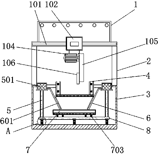
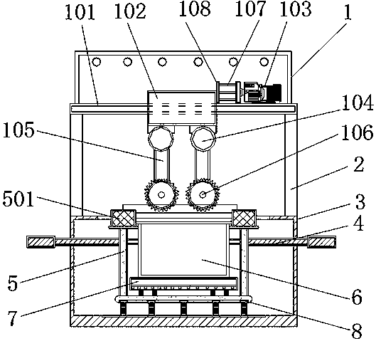
[0030] Embodiment 2, a double-head cutting device with mechanical synchronous chip removal, including a device main body 1, a column 2, a protective cover 3, a workbench 4, a support column 5, a deflector 6, a waste chip collection tank 7 and a limit plate 8. There is a device main body 1 above the protective cover 3, and the device main body 1 is connected to the protective cover 3 through the column 2. The hydraulic cylinder 103 is fixed on the device main body 1. The output end of the hydraulic cylinder 103 is connected with a hydraulic rod 107, and the hydraulic rod The other end of 107 is connected with push plate 108 , and push plate 108 is connected with sliding installation block 102 . The hydraulic cylinder 103 drives the hydraulic rod 107 to expand and contract, thereby driving the sliding mounting block 102 to move along the sliding rod 101 through the push plate 108, which is convenient for cutting the steel to be processed.

[0031] The lower part of the sliding m...

Embodiment 3

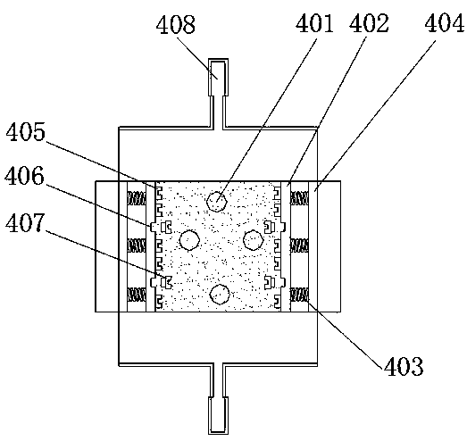
[0032]Embodiment 3, a double-head cutting device with mechanical synchronous chip removal, the two ends of the workbench 4 are provided with limit rods 408, the limit rods 408 pass through the protective cover 3 and cooperate with the protective cover 3, the limit rods 408 can be Sliding relative to the protective cover 3, the ends of the two limit rods 408 are provided with stoppers to limit the position, which ensures the level of the workbench 4 and prevents the processing of steel from being affected. The bottom of the workbench 4 is provided with a base plate, and the base plate is provided with a waste chip collection hole 401, and the waste chips generated in the process flow out through the waste chip collection hole 401, and four waste chip collection holes 401 are evenly and symmetrically arranged to ensure that waste during processing Chips flow down smoothly. Both sides of the base plate of the workbench 4 are provided with spring bases 404, the base plates of the ...


PUM


Abstract

The invention discloses a double-head cutting device for mechanical synchronous chip removal, and solves the problem that a currently used cutting device cannot fix steel materials with different shapes and specifications. The double-head cutting device comprises a device body, vertical columns, a sweeps collection groove and a limiting plate, wherein the device body is arranged above a protectioncover, the device body is connected with the protection cover through the vertical columns, the lower portion of the device body is provided with a sliding rod, the sliding rod is sleeved with a sliding mounting block cooperating with the sliding rod, the lower portion of the sliding mounting block is connected with two drive motors respectively, and the drive motors are connected with a cuttinggrinding wheel through a transmission mechanism; the limiting plate is slidably connected with the bottom of the protection cover, supporting columns are connected with the limiting plate, a workbenchis connected with the supporting columns, the upper portions of the supporting columns are slidably connected with the protection cover, the sweeps collection groove is formed in the limiting plate,and a drainage plate is arranged between the sweeps collection groove and the workbench. The double-head cutting device for the mechanical synchronous chip removal has the advantages that cutting is convenient, the steel materials with various specifications can be processed, and sweeps can be collected in the processing process.

Description

technical field [0001] The invention relates to the technical field of steel processing technology, in particular to a double-head cutting device with mechanical synchronous chip removal. Background technique [0002] Cutting refers to using a rotating multi-blade tool to cut a workpiece. It is a high-precision processing method. During work, the tool rotation is used as the main motion, and the workpiece moves as the feed motion. The workpiece can also be fixed, but the rotating tool must move at this time. [0003] The currently used cutting device cannot fix steels of different shapes and specifications, so that it is not convenient to cut steels of different shapes and specifications, which makes the cutting performance of steels relatively simple, making the cutting efficiency of steels not high, and cutting The process does not have the function of debris collection, which is not convenient for the operator to use. Contents of the invention [0004] The present inve...

Claims


Application Information

Patent Timeline
Patent Type & Authority Patents(China)
IPC IPC(8): B24B27/06B24B27/00B24B41/06B24B55/06B24B41/00B24B41/02
CPCB24B27/0076B24B27/06B24B41/007B24B41/02B24B41/06B24B55/06
Inventor 吴隆罗建敏
Owner ZHONGYUAN ENGINEERING COLLEGE
Why Eureka
Try Eureka