A binocular vision obstacle avoidance wheeled robot based on SLAM

A wheeled robot and binocular vision technology, applied in the field of computer vision, can solve problems such as poor real-time performance, susceptible to environmental interference, low precision, etc., to achieve improved real-time performance and accuracy, good real-time performance and high precision high effect

Pending Publication Date: 2018-11-27
DONGGUAN UNIV OF TECH
View PDF0 Cites 11 Cited by
  • Summary
  • Abstract
  • Description
  • Claims
  • Application Information

AI Technical Summary

Problems solved by technology

[0005] The purpose of the present invention is to overcome the defects and deficiencies of the mobile robot in the prior art, such as low precision, poor real-time p

Method used


Image

  • A binocular vision obstacle avoidance wheeled robot based on SLAM
  • A binocular vision obstacle avoidance wheeled robot based on SLAM
  • A binocular vision obstacle avoidance wheeled robot based on SLAM

Examples


Example Embodiment

[0051] Example 1

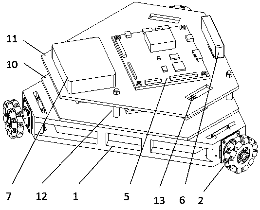
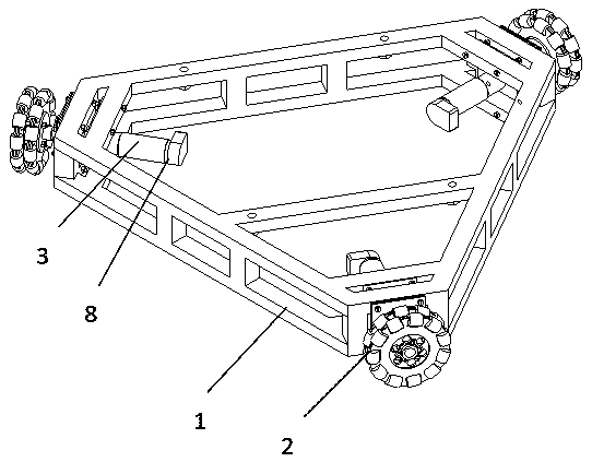
[0052] This embodiment provides a SLAM-based binocular vision obstacle avoidance wheeled robot, such as figure 1 , including a triangular aluminum alloy chassis frame 1, three symmetrically distributed wheels 2 arranged at the top corners of the chassis frame 1, and a driving device 3 for driving the wheels 2 to move. The chassis frame 1 is provided with an stm32 bottom control board 4, NVIDIA tx2 development board 5, a binocular vision camera 6, a power supply device 7 for providing power to the NVIDIA tx2 development board 5, an encoder 8 and an attitude sensor 9 for detecting the position and speed of the robot.

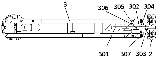
[0053] Specifically, as figure 2 and 3 , in this embodiment, the driving device 3 includes a MAXON motor 301 arranged on the chassis frame 1 and a flange 303 for fixing the drive shaft 302 and the wheel 2, the flange 303 is arranged on the flange bearing 304, and the motor The motor shaft of 301 is fixed to the transmission shaft 302 through...


PUM


Abstract

The invention relates to a binocular vision obstacle avoidance wheeled robot based on SLAM. The robot includes a chassis frame, wheels arranged on the chassis frame, driving means for driving the wheel movement, A low layer control board of that stm32 is arrange on the chassis frame, an NVIDIA tx2 development board, a binocular vision camera, a power supply device for supplying power to the stm32bottom control board and the NVIDIA tx2 development board, an encoder and a posture sensor for detecting the movement speed and the displacement of the robot; The stm32 bottom layer control board andthe binocular vision camera are respectively electrically connected with the NVIDIA tx2 development board; The driving device, the encoder and the attitude sensor are electrically connected with the bottom control board of the stm 32, respectively. The robot provided by the invention has the advantages of high precision, good real-time performance and is not easy to be disturbed by environment.

Description

technical field [0001] The invention belongs to the field of computer vision, and more specifically relates to a SLAM-based binocular vision obstacle avoidance wheeled robot. Background technique [0002] Existing technologies generally equip mobile robots with cameras, lidar or ultrasonic detectors to detect the position and shape of obstacles, and use certain path planning strategies to avoid obstacles. Ultrasonic ranging is based on the principle of measuring ultrasonic flight time. A piezoelectric or electrostatic transmitter generates an ultrasonic pulse with a frequency of tens of kHz to form a wave packet. The system detects a reverse sound wave higher than a certain threshold. The distance is calculated from the flight time to arrival. The principle of lidar sensing distance is based on the time-of-flight principle (TOF). The lidar includes a transmitter and a receiver. The transmitter uses laser light to illuminate obstacles, and the receiver receives the reverse l...

Claims


Application Information

Patent Timeline
IPC IPC(8): B25J5/00B25J9/16B25J13/08B25J19/04
CPCB25J5/007B25J9/1666B25J13/08B25J19/04
Inventor 田君王雷陈挺晓陈伟聪陈志豪苏大超朱永俊
Owner DONGGUAN UNIV OF TECH
Why Eureka
Try Eureka