Tidal power generation equipment

A tidal power generation and equipment technology, applied in wind power generation, mechanical equipment, hydropower generation, etc., can solve the problems of low degree of automation, high energy consumption, lack of continuity of equipment, etc., to maintain continuous usability, efficient use, and easy sustainable effects of sexual exploitation

Inactive Publication Date: 2018-11-27
石海光
View PDF0 Cites 1 Cited by
  • Summary
  • Abstract
  • Description
  • Claims
  • Application Information

AI Technical Summary

Problems solved by technology

[0003] The technical problem to be solved by the present invention is: in order to solve the problems of high energy consumption, low degree of automation, lack of effective use of the environment, inability to use wind energy and tidal combined power generation at the same time, and lack of continuity of equipment in existing tidal power generation equipment, the present invention Provided is a tidal power generation device, which effectively isolates a water storage tank from seawater by using a first baffle, a second baffle, a base, a diversion groove, a net, a main board, a limiting splint, and a water retaining mechanism set by a gate , the secondary storage tank is set up through the diversion groove, which can conveniently and effectively adjust the seawater and the storage tank, maintain the continuous usability of the equipment, maximize the use of tidal energy for power generation, and will not affect the marine ecological environment; use The main shaft, floating ring, isolation tube, threaded sleeve, end sleeve, transmission shaft, stabilizing device, fixed seat, lifting tube and auxiliary mechanism set up by the balance frame store the buoyancy of the water flow, prevent the main shaft from stopping, and facilitate the continuous protection of the equipment against the wind force. The invention solves the shortcoming that current tidal energy and wind energy combined power generation equipment cannot operate stably and continuously

Method used


Image

  • Tidal power generation equipment
  • Tidal power generation equipment
  • Tidal power generation equipment

Examples


Embodiment Construction

[0019] The present invention is described in further detail now in conjunction with accompanying drawing. These drawings are all simplified schematic diagrams, which only illustrate the basic structure of the present invention in a schematic manner, so they only show the configurations related to the present invention.

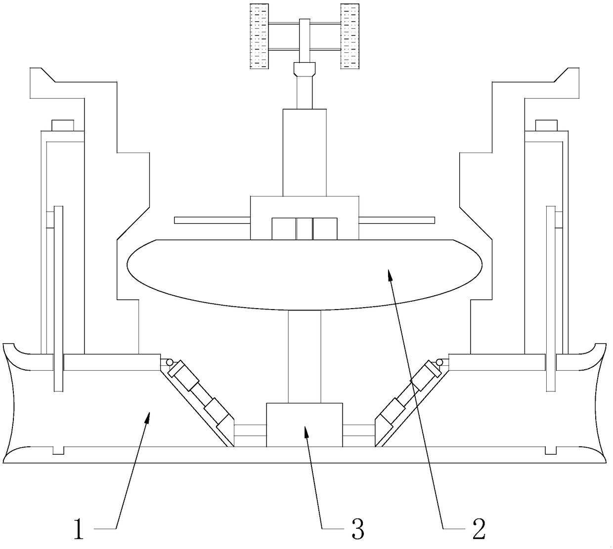
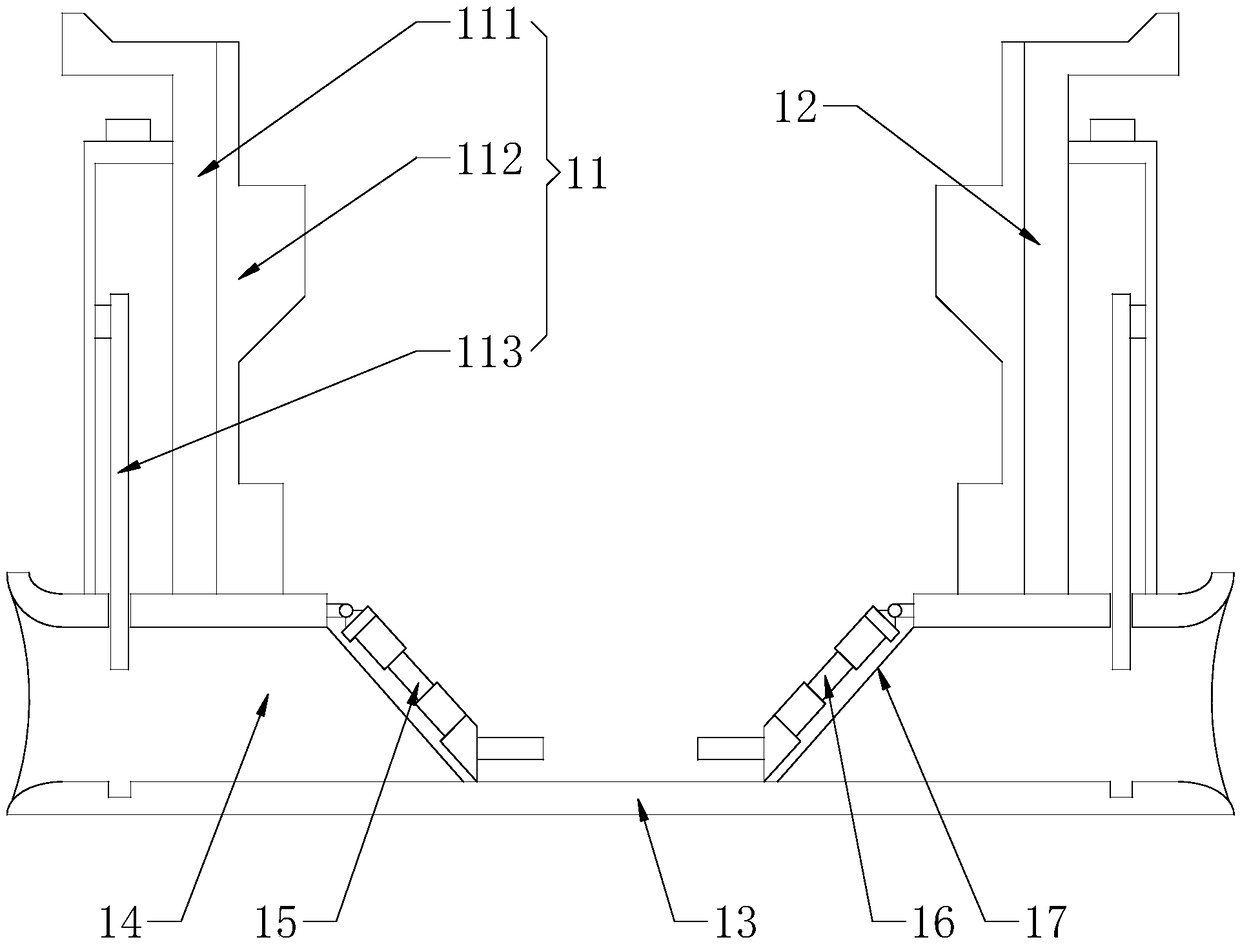
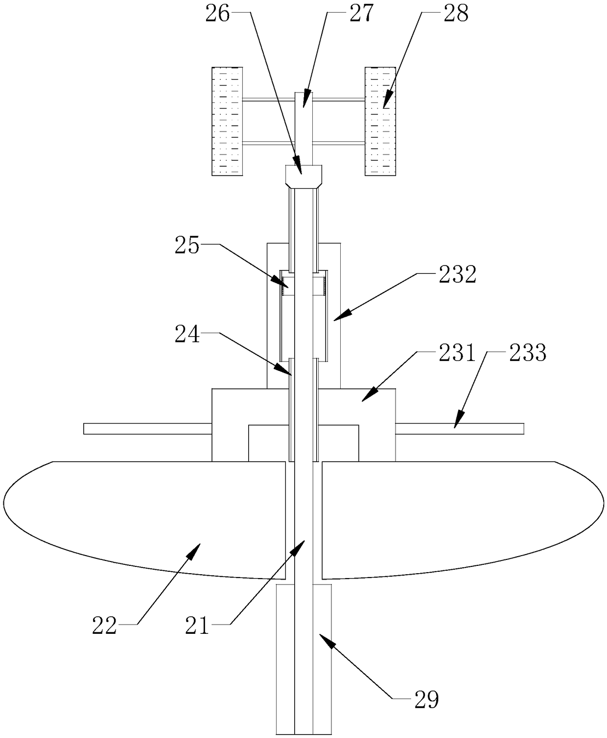
[0020] see Figure 1-3 , the present invention provides a technical solution: a tidal power generation equipment, including a water retaining mechanism 1 and an auxiliary mechanism 2, the auxiliary mechanism 2 is arranged inside the water retaining mechanism 1, a generator 3 is fixedly installed in the middle of the bottom of the water retaining mechanism 1, and The auxiliary mechanism 2 is fixedly installed on the upper end of the generator 3; the water retaining mechanism 1 includes a first baffle plate 11, a second baffle plate 12, a base 13, a diversion groove 14, a water turbine 15, a water turbine 2 16, a net 17, and a main board 111 , limit splint 112 ...


PUM


Abstract

The invention discloses tidal power generation equipment. The equipment comprises a water retaining mechanism and an auxiliary mechanism, wherein the auxiliary mechanism is arranged inside the water retaining mechanism, a power generator is fixedly arranged in the middle of the bottom of the water retaining mechanism, the auxiliary mechanism is fixedly arranged on the upper end of the power generator, the water retaining mechanism set by using a first baffle, a second baffle, a base, a diversion trench, a partition net, a main board, a limiting clamping plate and a gate can be conveniently, quickly and effectively adjusted between seawater and a reservoir to maintain the continuous use of the equipment; the auxiliary mechanism set by using a spindle, a floating ring, an isolation pipe, a threaded sleeve, an end sleeve, a transmission shaft, a smoothing device, a fixed seat, a lifting pipe and a balance frame stores the buoyancy of water flow to prevent the spindle from stopping rotating, thereby providing convenience for the continuous utilization of wind power. The tidal power generation equipment overcomes the shortcoming that current tidal energy and wind energy combined power generation equipment cannot stably or continuously run.

Description

technical field [0001] The invention relates to the related technical field of power generation equipment, in particular to tidal power generation equipment. Background technique [0002] The ocean tide phenomenon generated by the gravity of the moon contains endless energy. Using the seawater drop formed by the tide and the hydroelectric generating set to produce electric energy not only requires a large investment, but also the power output is restricted by the tidal periodicity and limited water level drop, and it will also affect the marine ecological environment. Therefore, ocean tidal energy has not yet been well developed and utilized. With the gradual consumption of limited traditional energy, the use of electric energy has gradually been promoted, but the amount of electric energy used is gradually increasing, and a larger amount of electric energy needs to be produced. Using geothermal energy, Diversified power generation technologies such as hydropower, tidal ene...

Claims


Application Information

Patent Timeline
Patent Type & Authority Applications(China)
IPC IPC(8): F03B13/26F03B11/00F03B17/02F03D9/25
CPCF03B11/00F03B13/26F03B17/02F03D9/008F03D9/25F05B2220/706Y02E10/20Y02E10/30Y02E10/72
Inventor 石海光
Owner 石海光
Why Eureka
Try Eureka