Particle image speed measuring device, method and system

A technology for particle image velocity measurement and area to be measured, which is used in measurement devices, fluid velocity measurement, velocity/acceleration/impact measurement, etc. It can solve the problem of limited laser output power, limited high-speed camera acquisition speed, and difficulty in shortening the pulse time interval. and other problems, to achieve the effect of improving temporal and spatial resolution, facilitating the measurement of unsteady flow, and improving the capability of velocity measurement

Inactive Publication Date: 2018-11-27
PLA PEOPLES LIBERATION ARMY OF CHINA STRATEGIC SUPPORT FORCE AEROSPACE ENG UNIV
View PDF8 Cites 16 Cited by
  • Summary
  • Abstract
  • Description
  • Claims
  • Application Information

AI Technical Summary

Problems solved by technology

[0005] (1) It is difficult to increase the output frequency and pulse energy of the PIV laser at the same time, which limits the time resolution of the measurement system
Although the Nd:YAG laser pulse time used in the current PIV system is very short, generally less than 10 ns, in order to realize the velocity measurement, the laser needs to illuminate the flow field at least twice, and the pulse time interval is limited by the laser output power. Energy is a set of contradictions, and the pulse time interval is difficult to shorten
Coupled with the limited frame rate of high-speed cameras, the shortest time between two frames of common domestic high-speed cameras was only about 1 microsecond before, which also limits the time resolution of the PIV system to the order of 1 microsecond
[0006] (2) Limited by the acquisition speed of high-speed cameras, it is difficult to realize the PIV measurement method with more than two channels
If the time resolution of the PIV system exceeds the order of 1 microsecond, the recording speed of the camera is required to exceed 1MHz, and it can record multiple frames continuously. The current development level of high-speed cameras is still difficult to meet this demand

Method used


Image

  • Particle image speed measuring device, method and system
  • Particle image speed measuring device, method and system
  • Particle image speed measuring device, method and system

Examples


Embodiment 1

[0110] Embodiment 1 Particle Image Velocimetry Device

[0111] The device described in this embodiment includes: a laser unit that emits laser light to the area to be measured;

[0112] an acquisition unit, for acquiring particle images of the region to be measured;

[0113] A control unit, the control unit is electrically connected to the laser unit and the acquisition unit, and controls the action and / or state of the laser unit and the acquisition unit;

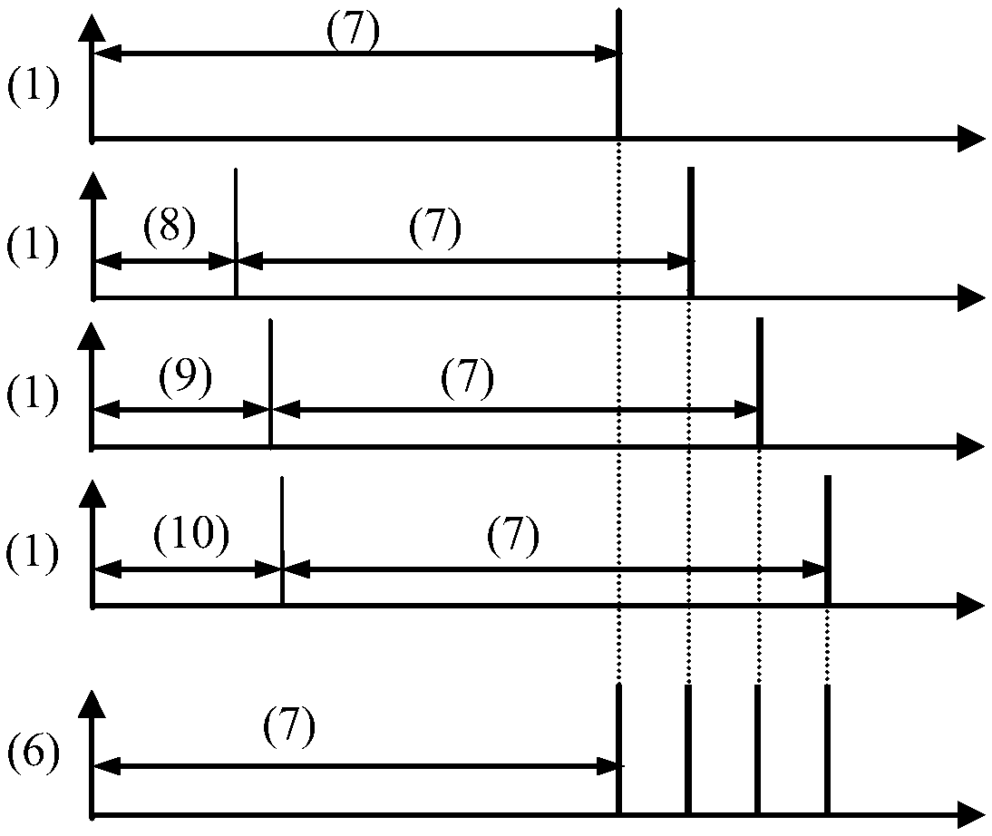
[0114] Wherein, the laser unit emits at least two laser beams, and the light output timing of each laser beam satisfies an increasing or decreasing relationship;

[0115] The acquisition unit includes at least two acquisition channels, and the acquisition time of each acquisition channel satisfies an increasing or decreasing relationship, and respectively corresponds to the light emitting time sequence of each beam of laser light in the laser unit.

[0116] As one of the specific implementations, the delay time of the fir...

Embodiment 2

[0143] Embodiment 2 particle image velocimeter

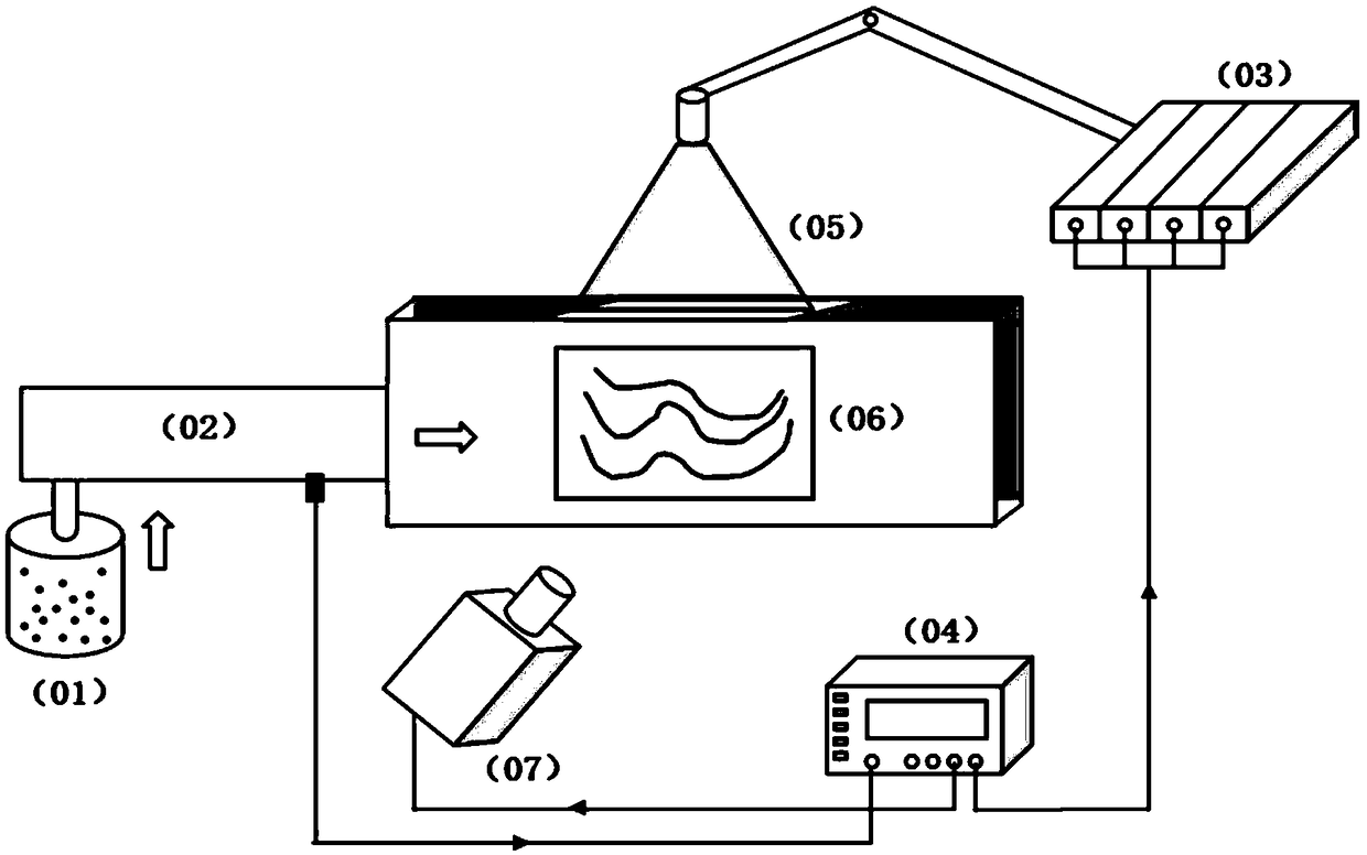
[0144] The particle image velocimetry device described in this embodiment, such as figure 1 shown.

[0145] The particle image velocimetry device includes: four lasers, a digital pulse signal generator, and a four-channel high-speed enhanced PCO camera.

[0146] The laser is a nanosecond pulsed laser.

[0147] The digital pulse signal generator is electrically connected with the laser and the four-channel high-speed enhanced PCO camera respectively, and controls the light emission time of each laser and the collection time of each channel respectively.

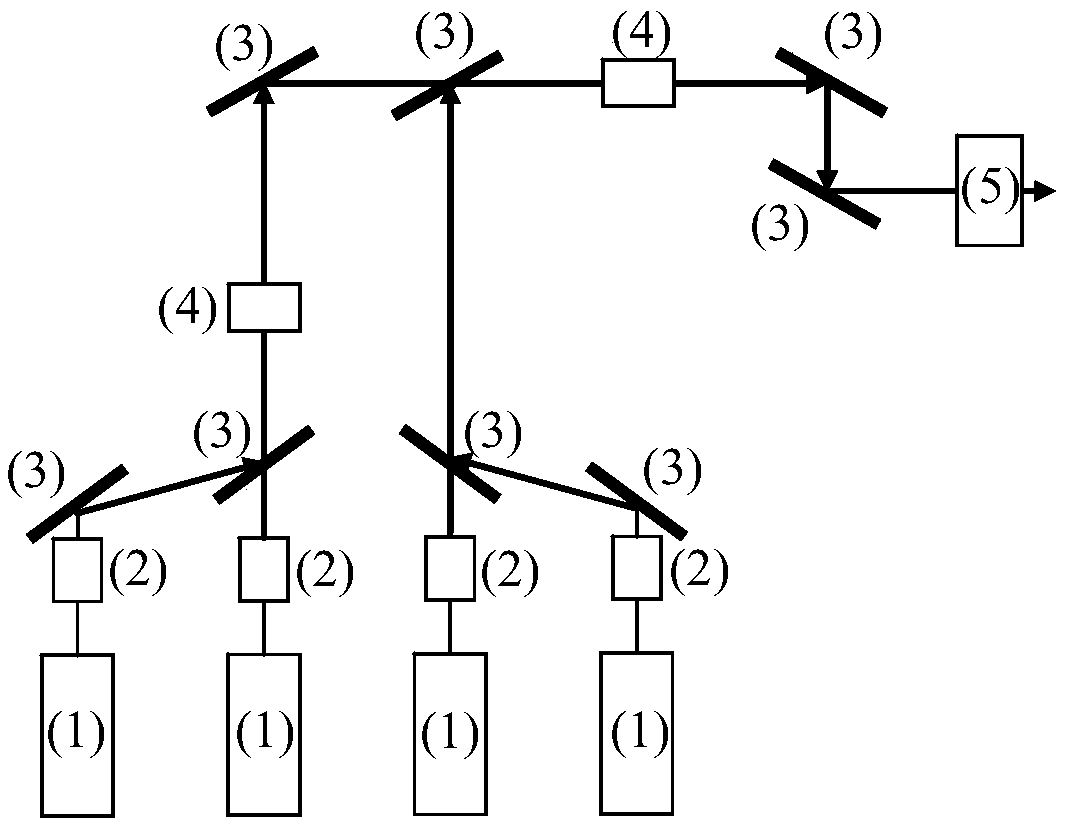
[0148] The lasers emit light according to the light emitting time sequence, and each beam of light is combined into a piece of light through beam combining technology to irradiate the area to be measured.

[0149] Each channel of the four-channel high-speed enhanced PCO collects tracer particle images of the area to be measured in time sequence.

[0150] The tracer particle ...

Embodiment 3

[0154] Embodiment 3 particle image velocimetry device

[0155] The difference between the device described in this embodiment and Embodiment 2 is that the laser is a Nd:YAG laser;

[0156] The tracer particles are nano titanium dioxide powder.


PUM


Abstract

The invention discloses a particle image speed measuring device, method and system. The device comprises a laser unit for emitting the laser to a to-be-measured region; an acquisition unit for acquiring the particle image of the to-be-measured region; a control unit electrically connected with the laser unit and the acquisition unit to control the movement and/or state of the laser unit and the acquisition unit, wherein the laser unit emits at least two beams of laser, and the light emitting time sequence between the laser beams satisfies the incremental or decreasing relation; the acquisitionunit at least comprises two acquisition channels, and the acquisition time of each acquisition channel meets the incremental or decreasing relation, and corresponds to the light emitting time sequence of each beam in the laser unit in sequence. The device and the method overcome the contradiction that the light emitting frequency and the pulse energy of a single laser are difficult to improve atthe same time, the problem of high-speed photography is solved, and the resolution of the measurement system is greatly improved.

Description

technical field [0001] The application relates to a particle image velocity measurement device, method and system, belonging to the technical field of aerodynamic experiments. Background technique [0002] Particle Image Velocimetry (PIV) technology is a transient, multi-point, non-contact hydrodynamic velocity measurement method. Its biggest feature is that it breaks through the limitations of single-point velocity measurement technology. The velocity distribution information on a large number of spatial points is recorded, and further processing can obtain the distribution of flow field characteristic parameters such as vorticity, streamline and isokinetic line of the flow field, which has high measurement accuracy. In addition to scattering tracer particles to the flow field, all measuring devices do not enter the flow field, and have very little impact on the flow field. Therefore, it has become a widely accepted and popular fluid dynamics measurement technology. It has...

Claims


Application Information

Patent Timeline
Patent Type & Authority Applications(China)
IPC IPC(8): G01P5/22
CPCG01P5/22
Inventor 王殿恺王伟东文明李倩
Owner PLA PEOPLES LIBERATION ARMY OF CHINA STRATEGIC SUPPORT FORCE AEROSPACE ENG UNIV
Why Eureka
Try Eureka