AR (Augmented Reality) optical device and wearable AR device

An optical device and spectroscopic technology, used in optics, optical components, instruments, etc., can solve the problems of low utilization of light energy, inability to see the eyes, low light transmittance, etc., to improve sociality, improve external visibility, The effect of improving light transmittance

Pending Publication Date: 2018-11-27
TAIRUO TECH BEIJING CO LTD
View PDF0 Cites 26 Cited by
  • Summary
  • Abstract
  • Description
  • Claims
  • Application Information

AI Technical Summary

Problems solved by technology

[0004] The existing AR optical device has the following defects: part of the light of the image light passes through the beam splitter 3, a part of the light is reflected light, and a part of the light is transmitted light, and the reflected light through the beam splitter 3 is directed to the curved half mirror 4, and part of the light is retransmitted Reflected by the curved half-reflector 4 and directed to the beam splitter 3, the light from the image source 11 is reflected and transmitted, causing a large amount of light to be lost. When the wearer observes the surrounding environment through the device, the light transmittance of the image source light Low light energy utilization rate, at the same time, due to a large number of interfering light sources, the wearer's eyes cannot be seen from the outside, resulting in poor sociability

Method used


Image

  • AR (Augmented Reality) optical device and wearable AR device
  • AR (Augmented Reality) optical device and wearable AR device
  • AR (Augmented Reality) optical device and wearable AR device

Examples


Embodiment 1

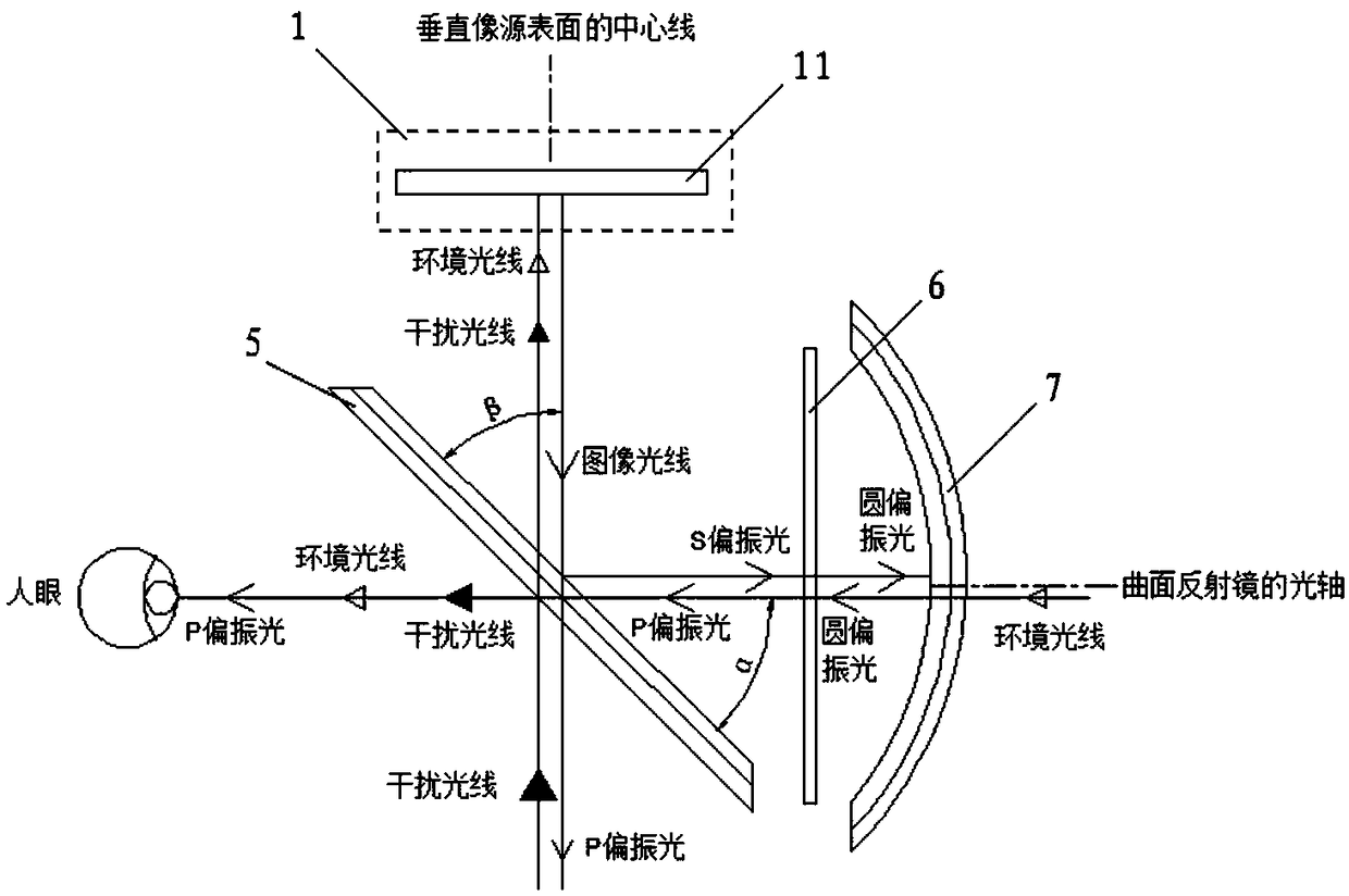
[0040] This embodiment provides an AR optical device, such as figure 2 As shown, the AR optical device includes an image projection device 1 , a bandpass polarization beam splitter 5 , a wave plate assembly 6 and a mirror. Wherein, the image projection device 1 includes an image source 11, the image light emitted from the image source 11 is divided into the polarized light in the first direction and the polarized light in the second direction through the band-pass polarization beam splitter 5, and the outgoing polarized light in the first direction The direction is away from the image source 11 , and the polarized light in the second direction goes to the mirror, is reflected by the mirror, goes to the band-pass polarization beam splitter 5 , and passes through the band-pass polarization beam splitter 5 . In this embodiment, the polarized light in the first direction may be P-polarized light, and the polarized light in the second direction may be S-polarized light.

[0041] ...

Embodiment 2

[0062] An embodiment of the present invention also provides a wearable AR device, including a clip and the AR optical device described in Embodiment 1 or Embodiment 2 above.

[0063] The wearable AR device may be but not limited to AR glasses, AR helmet or AR mask. When the wearable AR device is AR glasses, the clip is a frame, and the AR optical device is installed on the frame, which is equivalent to the positions of two lenses. When the wearable AR device is an AR helmet, the clip member may be a helmet shell, and the AR optical device is installed on the front window of the helmet shell.

[0064] The wearable AR device of this embodiment is provided with the above-mentioned AR optical device, and the AR optical device adopts a polarized optical path assembly, which includes a band-pass polarization beam splitter, a wave plate assembly, and a mirror arranged in sequence, and the image projection device is located in the band-pass above or below the polarizing beamsplitter....


PUM

PropertyMeasurementUnit
Thicknessaaaaaaaaaa

Abstract

The invention provides an AR (Augmented Reality) optical device and a wearable AR device, which belong to the technical field of augmented reality imaging. The AR optical device comprises a band-passpolarizing beam splitter and a reflector, image light emerging from an image source is divided into polarized light in a first direction and polarized light in a second direction after passing throughthe band-pass polarizing beam splitter, wherein the emerging direction of the polarized light in the first direction gets away from the image source, and the polarized light in the second direction goes to the reflector, then, after being reflected by the reflector, goes to the band-pass polarizing beam splitter, is transmitted by the band-pass polarizing beam splitter, and finally goes to humaneyes. The light within a wavelength passband range is polarized and splitted by a band-pass polarizing beam splitting film, while the light outside the wavelength passband range can be completely transmitted, consequently, while the efficiency of light source energy utilization is not decreased, the light transmittance for world observation by a wearer is increased, moreover, the external visibility of the eyes of the wearer is increased, and thereby sociability is increased.

Description

technical field [0001] The present invention relates to the technical field of augmented reality imaging, in particular to an AR optical device and a wearable AR device. Background technique [0002] AR (Augmented Reality, Augmented Reality) is also known as mixed reality. Its principle is to apply virtual information to the real world through computer technology. The real environment and virtual objects are superimposed on the same picture or space in real time. [0003] Currently, people can interact with the real world through wearable devices, such as AR glasses or AR helmets. Such as figure 1 A schematic structural diagram of an AR optical device in an existing AR glasses or an AR helmet is shown, as shown in figure 1 As shown, the existing AR optical device optical system includes an image source 11, a beam splitter 3, a curved half mirror 4 and a lens 12 positioned above the beam splitter 3, the image source 11 is arranged on the top of the optical system, and the i...

Claims


Application Information

Patent Timeline
IPC IPC(8): G02B27/01
CPCG02B27/0101G02B27/0172G02B2027/0178G02B27/0018G02B5/288G02B2027/0194G02B1/11G02B27/283G02B2027/0114G02B5/3083
Inventor 肖冰徐驰
Owner TAIRUO TECH BEIJING CO LTD
Why Eureka
Try Eureka