Aircraft height control method and system based on radar technology

A technology for altitude control and aircraft, applied in the field of radar systems, it can solve the problems such as the more demanding accuracy requirements of the multi-frequency to dual-frequency method, the frequency limit of the transmission signal for the altitude measurement distance, and the many frequency points of the secondary phase method. Facilitate high-precision control, improve phase measurement accuracy, and increase the effect of distance measurable range

Inactive Publication Date: 2018-11-27
ANHUI NIKOLA ELECTRONICS TECH CO LTD
View PDF12 Cites 5 Cited by
  • Summary
  • Abstract
  • Description
  • Claims
  • Application Information

AI Technical Summary

Problems solved by technology

[0004] At present, multi-frequency radar is widely used in height measurement. However, these multi-frequency radar methods still have shortcomings: the dual-frequency phase comparison method has the contradiction of expanding the ranging range and improving accuracy; the staggered multi-frequency method needs to transmit multiple sets of dual-frequency The algorithm has a large amount of calculation and the system is complex; the multi-frequency to dual-frequency method has strict requirements on the ranging accuracy; the quadratic phase method also needs more transmitting frequency points, etc.
However, multi-frequency measuring ruler switching will reduce the real-time performance of the measurement, and introduce measurement errors caused by mechanical and electrical jitter caused by measuring ruler switching, and the switching speed (several seconds) is slower than the target state change (such as vibrating bridges, tall buildings, etc.)
[0005] For example, the application publication number is 106681344A, a kind of

Method used


Image

  • Aircraft height control method and system based on radar technology
  • Aircraft height control method and system based on radar technology
  • Aircraft height control method and system based on radar technology

Examples


Example Embodiment

[0034] The technical solutions in the embodiments of the present invention will be clearly and completely described below in conjunction with the accompanying drawings in the embodiments of the present invention. Obviously, the described embodiments are only a part of the embodiments of the present invention, rather than all the embodiments. Based on the embodiments of the present invention, all other embodiments obtained by those of ordinary skill in the art without creative work shall fall within the protection scope of the present invention.
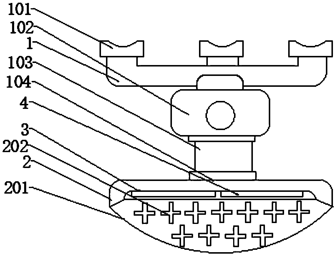
[0035] Such as figure 1 As shown, the present invention provides an aircraft height control method and system based on radar technology, including an omnidirectional rotating base 1 for fixed installation on the aircraft, and the omnidirectional rotating base 1 is fixed upside down on the lower surface of the aircraft, In addition, a shielding protective cover 2 for reducing external signal interference is installed on the omnidirectional...


PUM


Abstract

The invention discloses an aircraft height control method and system based on a radar technology, and the system includes an omnidirectional rotating base and a shielding protective cover, a radar ranging unit and a feedback adjusting unit are arranged in the shielding protective cover, and the radar ranging unit comprises an antenna front end, the antenna front end comprises a transmitting antenna connected with the transmitting channel and a receiving antenna connected with the receiving channel, the input end of the transmitting antenna is connected with a power amplifier used for amplifying and driving, and the output end of the receiving antenna is connected with a low-noise amplifier; the input channel end of the antenna front end is connected with a transmitting and modulating unit,the output channel end of the antenna front end is connected with a phase measurement unit based on a high-precision time measurement technology; the output end of the phase measuring unit is furtherconnected with a wireless signal emitter used for being communicated with the feedback adjusting unit. According to the invention, the measuring precision and the ranging range of the radar ranging system are effectively improved, the closed-loop feedback adjustment on the height of the aircraft is realized, and the control precision is high and the performance is good.

Description

technical field [0001] The invention relates to the field of radar systems, in particular to a radar technology-based aircraft altitude control method and system. Background technique [0002] In the control system of aircraft (such as UAV), altitude control is realized based on the altitude measured in real time, so the stability of altitude control mainly depends on the measurement accuracy and real-time performance of the altimeter. At present, the altitude is usually measured directly by the altimeter in the aircraft. There are many types of altimeters, such as GPS, barometer, ultrasonic sensor, etc. Among them, GPS is only suitable for altitude measurement when there are no trees or buildings to block and the signal is stable. , the relative altitude accuracy is low, and the update frequency of GPS data is 1Hz, and the real-time performance is poor; the barometer is easily affected by the airflow, and the height measurement drifts greatly; Accurate height determination...

Claims


Application Information

Patent Timeline
IPC IPC(8): G05D1/04G01S13/08G01S13/88
CPCG01S13/08G01S13/88G05D1/042
Inventor 马德山陈宏松夏森何李元
Owner ANHUI NIKOLA ELECTRONICS TECH CO LTD
Why Eureka
Try Eureka