Installation method of anti-jamming optical fiber perimeter guard detector

An installation method and optical fiber perimeter technology, applied in the direction of alarms by breaking/disturbing the straightened rope/metal wire, mechanical activation of anti-theft alarms, etc., can solve the problem of increasing the false alarm rate of the detector and affecting the detection of the detector. , security accuracy and poor accuracy, etc., to increase the anti-interference factor, increase the sensing area, and overcome the effects of their own errors

Inactive Publication Date: 2018-11-27
CHINA PETROLEUM & CHEM CORP +1
View PDF7 Cites 2 Cited by
  • Summary
  • Abstract
  • Description
  • Claims
  • Application Information

AI Technical Summary

Problems solved by technology

[0003] 1. Climatic factors such as strong wind and heavy rain will increase the false alarm rate of the detector
[0004] 2. The impact of birds and small animals increases the probability of system false positives
[0005] 3. Interference caused by noise, mechanical vibration and other interference factors in the layout environment
[0006] 4. The fixing method is improper, and the binding is too tight, resulting in a decrease in sensitivity
[0007] 5. Within the unit length, the length used by the fiber optic detector is less than the detection error of the detector itself, resulting in inaccurate defense zones
[0008] 6. Vegetation near the perimeter affects detector detection and causes false alarms
[0010] The defense zone deployment and positioning method of the perimeter defense system disclosed in this patent document uses multiple defense zone composites, which can prevent the failure of the defense zone equipment from causing the entire security system to fail, and ensure system reliability. However, the influence of the external environment often causes the problem of false alarms in the defense zone. The precision and accuracy of security are poor

Method used


Image

  • Installation method of anti-jamming optical fiber perimeter guard detector

Examples


Embodiment 1

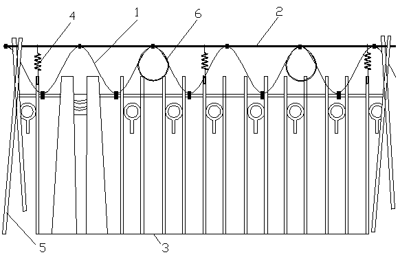
[0040] A method for installing an anti-interference optical fiber perimeter protection detector, comprising the following steps:

[0041] a. According to the form of the surrounding wall of the factory area, select the spring for laying the fixed linear vibration detector 1, and install it along the surrounding wall of the factory area;

[0042] b. The linear vibration detector 1 is laid sinusoidally through the spring support. According to the requirements of the linear vibration detector 1 on the strength and flexibility of the straight spring steel wire above the spring, the steel wire is selected as galvanized round steel 2;

[0043] c. In combination with the requirements of the size of the defense zone, determine the length of the linear vibration detector 1 within the unit length;

[0044] d. Test whether the position of the defense zone is consistent with the actual position according to the defense zone segment, and adjust the sensitivity of the linear vibration detec...

Embodiment 2

[0047] A method for installing an anti-interference optical fiber perimeter protection detector, comprising the following steps:

[0048] a. According to the form of the surrounding wall of the factory area, select the spring for laying the fixed linear vibration detector 1, and install it along the surrounding wall of the factory area;

[0049] b. The linear vibration detector 1 is laid sinusoidally through the spring support. According to the requirements of the linear vibration detector 1 on the strength and flexibility of the straight spring steel wire above the spring, the steel wire is selected as galvanized round steel 2;

[0050] c. In combination with the requirements of the size of the defense zone, determine the length of the linear vibration detector 1 within the unit length;

[0051] d. Test whether the position of the defense zone is consistent with the actual position according to the defense zone segment, and adjust the sensitivity of the linear vibration detec...

Embodiment 3

[0057] A method for installing an anti-interference optical fiber perimeter protection detector, comprising the following steps:

[0058] a. According to the form of the surrounding wall of the factory area, select the spring for laying the fixed linear vibration detector 1, and install it along the surrounding wall of the factory area;

[0059] b. The linear vibration detector 1 is laid sinusoidally through the spring support. According to the requirements of the linear vibration detector 1 on the strength and flexibility of the straight spring steel wire above the spring, the steel wire is selected as galvanized round steel 2;

[0060] c. In combination with the requirements of the size of the defense zone, determine the length of the linear vibration detector 1 within the unit length;

[0061] d. Test whether the position of the defense zone is consistent with the actual position according to the defense zone segment, and adjust the sensitivity of the linear vibration detec...


PUM


Abstract

The invention discloses an installation method of an anti-jamming optical fiber perimeter guard detector, belonging to the technical field of security engineering. The method is characterized by comprising the following steps: a. selecting a spring for laying a fixed linear vibration detector, and installing along a perimeter fence wall of a plant area; b. using a sinusoidal way to lay the linearvibration detector by means of a spring bracket; c. determining the length of the linear vibration detector within per unit length by combining the requirement for the size of a defense area; d. testing whether the position of the defense area is coincided with the actual position or not according to the division of the defense area, and adjusting the sensitivity of the linear vibration detector by means of a software background. The installation method provided by the invention changes a sensing area with a function of segment detection into one surface from one point, thus effectively overcoming the environmental influence, and reducing the false alarm rate; system software is cooperatively used for adjusting the sensitivity of the individual defense area for different environments, so that the environmental interference resistance of the linear vibration detector can be enhanced, and the detection accuracy and accuracy are greatly improved.

Description

technical field [0001] The invention relates to the technical field of security engineering, in particular to an installation method of an anti-interference optical fiber perimeter protection detector. Background technique [0002] The optical fiber perimeter security system adopts phase-sensitive optical time-domain reflection technology, and realizes the vibration monitoring along the entire optical cable through the time difference between the vibration information reflected back to the system and the optical pulse. Through the propagation speed of the pulse laser in the optical fiber and the time interval of the back light echo, the vibration point is located, and the position information is obtained through monitoring. The installation of the linear vibration detector plays a key role in the detection accuracy of the system, and the installation method determines whether the alarm location is accurate. Generally speaking, the linear vibration detector is fixed in the f...

Claims


Application Information

Patent Timeline
Patent Type & Authority Applications(China)
IPC IPC(8): G08B13/12
Inventor 崔吉宏陈镭张建东周家伟曹文全蒋波曹振涛王希刚徐秦川李景辉
Owner CHINA PETROLEUM & CHEM CORP
Why Eureka
Try Eureka