
Voltage Paralleling and Switching Method of Localized Secondary Equipment for Substation Protection and Measurement and Control

A technology for secondary equipment and substations, applied to emergency protection circuit devices, electrical components, circuit devices, etc., can solve problems such as difficult maintenance work, high coupling degree of loop information, secondary voltage reverse transmission, etc., and achieve a clear functional structure , suitable for a wide range of effects

Active Publication Date: 2021-01-29
STATE GRID HUNAN ELECTRIC POWER +2
View PDF2 Cites 0 Cited by
  • Summary
  • Abstract
  • Description
  • Claims
  • Application Information

AI Technical Summary

Problems solved by technology

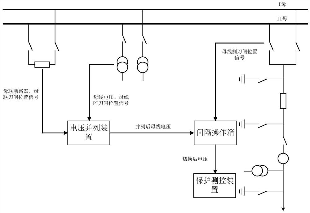
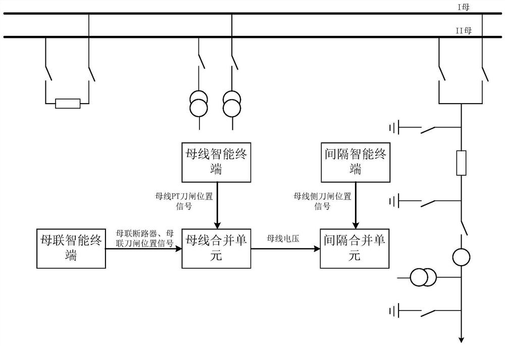
[0010] In summary, in the actual application of the project, there is an urgent need for a new and effective substation protection, measurement and control on-site secondary equipment voltage paralleling and switching function realization method to solve the voltage paralleling achieved by the current conventional substation through the electrical circuit There are hidden dangers such as secondary voltage reverse transmission and secondary voltage loss of the AC bus in the switching function mode. The voltage parallel and switching function mode realized by the bus PT merging unit in the smart substation has the problems that the coupling degree of loop information is too high and the maintenance work is difficult to carry out. Improve the automation level of secondary equipment management, operation and maintenance

Method used


Image

  • Voltage Paralleling and Switching Method of Localized Secondary Equipment for Substation Protection and Measurement and Control
  • Voltage Paralleling and Switching Method of Localized Secondary Equipment for Substation Protection and Measurement and Control
  • Voltage Paralleling and Switching Method of Localized Secondary Equipment for Substation Protection and Measurement and Control

Examples


Embodiment 1

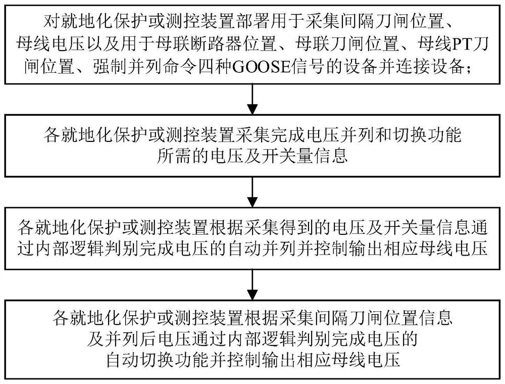
[0058] and figure 1 and figure 2 The above-mentioned two prior art solutions are different. The voltage paralleling and switching functions of the local secondary equipment voltage paralleling and switching method for substation protection and measurement and control in this embodiment are all realized in the local protection, measurement and control device. The position information of the bus tie circuit breaker, bus tie switch, bus PT switch and other position information required for voltage paralleling and switching is converted into GOOSE information after being collected by the local bus tie protection device or the bus measurement and control device or the dedicated local open input module Send it to the local protection, measurement and control device; the bus voltage and the position of the bay side knife switch are independently collected by each local protection, measurement and control device. Such as image 3 As shown, the implementation steps of the substation...

Embodiment 2

[0090]This embodiment is basically the same as Embodiment 1, and the main difference is that this embodiment does not include the in-situ bus tie protection device 4 and the bus measurement and control device 6, and the in-situ bus connection protection device 4 and the bus measurement and control device 6 The signal acquisition of bus tie circuit breaker position, bus tie knife switch position and bus PT knife switch position signal can also be realized through a dedicated in-situ switch-in module, see Embodiment 2 for details. Specifically: the first dedicated on-site switch-in module is deployed on the protection network, and the position of the bus tie circuit breaker, the bus The signals of the position of the joint knife switch and the position of the busbar PT knife switch are all realized through the first dedicated on-site opening module; the second dedicated on-site opening module is deployed on the station control layer network, and the signals collected by the on-si...

Embodiment 3

[0092] The basic idea of ​​this embodiment is the same as that of Embodiment 1, but the substation network structure it targets is different. In this embodiment, it is specifically aimed at in-situ protection of substations, measurement and control two-layer one network, and SV / GOOSE / MMS triple-network integration A substation protection and measurement and control in-situ secondary equipment voltage paralleling and switching method realized by a grid structure. The implementation steps of the substation protection and measurement and control in-situ secondary equipment voltage paralleling and switching method in this embodiment include:

[0093] S1) if Figure 10 As shown, for substations based on local protection, measurement and control two-layer one network and SV / GOOSE / MMS three-in-one grid structure, the substation is used to perform local protection or measurement and control for secondary equipment voltage paralleling and switching The device deploys a network interfa...


PUM


Abstract

The invention discloses a substation protection and measurement and control in-situ secondary equipment voltage paralleling and switching method. The implementation steps include deploying for in-situ protection or measurement and control devices to access the position of the interval switch, the bus voltage, and the bus tie circuit breaker. location, bus coupler switch position, bus PT switch position, equipment for forced parallel command and connected equipment, each localized protection or measurement and control device collects information required to complete voltage paralleling and switching functions; each localized protection or measurement and control device According to the collected information, the automatic paralleling of the voltage is completed through the internal logic judgment and the corresponding bus voltage is controlled to be output. The invention has wide adaptability, clear functional structure, good safety, is convenient for maintenance, can ensure the protection integrity of the secondary equipment of the busbar where the fault is located, and reduces the probability of misoperation and refusal of protection.

Description

technical field [0001] The invention relates to a substation bus voltage paralleling and switching technology, in particular to a method for realizing the voltage paralleling and switching functions of protection, measurement and control localized secondary equipment in single bus section and double bus wiring mode. Background technique [0002] The single-bus section and double-bus wiring methods are widely used in large and medium-sized substations of 220 kV and below. They have the advantages of reliable power supply, convenient expansion, and flexible operation modes. Switch between different buses to ensure uninterrupted power supply for important loads. [0003] When the two sections of busbars are running in parallel, the bus tie circuit breaker and the isolating switch on both sides are closed. Assuming that the PT of bus I is out of operation due to failure or maintenance, the voltage of PT of bus II needs to be paralleled to that of bus I The PT voltage is used fo...

Claims


Application Information

Patent Timeline
Patent Type & Authority Patents(China)
IPC IPC(8): H02J3/00H02H7/22H02H7/26
CPCH02H7/22H02H7/267H02J3/0073
Inventor 李辉黄勇敖非宁春海姜雯君梁文武朱维钧刘海峰余斌李刚徐浩臧欣潘伟刘宇郭思源吴晋波洪权沈杨
Owner STATE GRID HUNAN ELECTRIC POWER
Learn More