
Vertical type assembling die assembly

A combined mold, vertical technology, applied in the direction of mold auxiliary parts, manufacturing tools, ceramic molding machines, etc., can solve the problems of large consumption of consumables, different regional amplitudes of the touch table, and large floor space, to meet the specifications and requirements. Design requirements, novel design science, small footprint effect

Active Publication Date: 2018-11-30
曲周县和盛新型建筑安装有限公司
View PDF6 Cites 3 Cited by
  • Summary
  • Abstract
  • Description
  • Claims
  • Application Information

AI Technical Summary

Problems solved by technology

However, the traditional prefabrication method of flat plate formwork is difficult to meet the modern manufacturing requirements of sophisticated, high-quality and fast manufacturing. Due to the different parts of the components used, there are large differences in external dimensions. To manufacture plate components of different specifications, it is necessary to make a model that matches the formwork. There are many types of models, labor-intensive, time-consuming, and high consumption of consumables. In addition, the use of flat mold tables has disadvantages such as large floor space, complicated process flow, serious waste of turnover materials, low manufacturing efficiency, and high energy consumption for maintenance.
[0003] In addition, although the flat-panel mold table is equipped with self-vibration equipment or vibrating stations, problems that have not been solved so far have been exposed in the specific vibration process. Because the plane size of the flat-panel mold table is fixed, the plane size of the prefabricated components changes. Therefore, it is rare to achieve uniform distribution of components on the flat-panel touch table, resulting in uneven regional amplitude of the touch table, resulting in displacement deformation and looseness of components, which directly affects product quality

Method used


Image

  • Vertical type assembling die assembly
  • Vertical type assembling die assembly
  • Vertical type assembling die assembly

Examples


Embodiment Construction

[0027] Below in conjunction with embodiment the present invention is described in further detail:

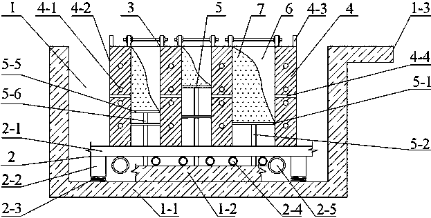
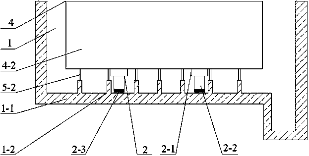
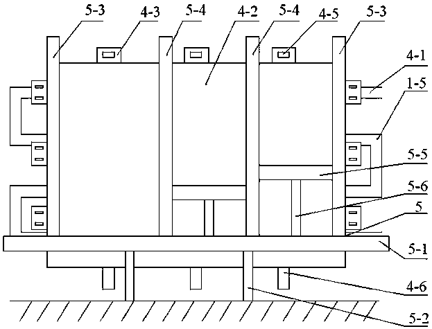
[0028] A vertical combination mold assembly, such as Figure 1-4 As shown, it includes a manger-type shell-type station 1 and a vibrating device 2 arranged in the shell-type station 1 and a vertical mold 3 arranged on the vibrating device 2. The setting of the vibrating device 2 can promote concrete in the The flow in the vertical mold 3 and the vibration of the concrete are strengthened to increase its compactness, so as to ensure that the surface of the manufactured plate member 6 is smooth, the interior is densely combined, and the product quality is guaranteed.

[0029] The shell-type workstation 1 can be built on the ground, underground or semi-underground, and the material can be steel or other building materials. The top of the shell-type station 1 is provided with an operating platform 1-3 that is at the same height as the vertical mold 3, and the operating platform 1-3...


PUM


Abstract

The invention discloses a vertical type assembling die assembly which is suitable for prefabricating a concrete plate type component used for various constructional projects, and comprises the step ofprefabricating an outer wall insulation board, a pair of polished panels and a bearing fill integrated plate. The assembly comprises a manger-shaped shell type station as well as a vibration device arranged in the shell type station and a vertical type die arranged on the vibration device, the vertical type die comprises a vertical type template, which is vertically arranged on the vibration device, and a plate model adjusting piece, a model space is enclosed between the plate model adjusting piece and the adjacent vertical type template, and concrete is poured in the model space to make a plate type component. According to the vertical type assembling die assembly, slab model table paving molding is changed into vertical type pouring molding, grinding is not required for self-forming a polished surface, a material consuming support die is not required, meanwhile, plate type components with different specifications can be manufactured, the natural vibration is dense, natural evaporation is performed for maintenance, the component quality is stable and reliable, the equipment operates safely and is easy and convenient to operate, and a new manufacturing method is provided for the industry to develop towards industrialization, so that to strongly advocate the vertical type assembling die assembly is necessary.

Description

technical field [0001] The invention relates to the field of construction engineering, in particular to a vertical combined mold assembly. Background technique [0002] Prefabricated buildings have the characteristics of short construction period, high installation accuracy, and little influence from environmental factors. Therefore, the manufacturing accuracy and production capacity of prefabricated components are high. However, the traditional prefabrication method of flat plate formwork is difficult to meet the modern manufacturing requirements of sophisticated, high-quality and fast manufacturing. Due to the different parts of the components used, there are large differences in external dimensions. To manufacture plate components of different specifications, it is necessary to make a model that matches the formwork. There are many types of models, labor-intensive, time-consuming, and large consumption of consumables. In addition, the use of flat mold tables has disadvant...

Claims


Application Information

Patent Timeline
Patent Type & Authority Applications(China)
IPC IPC(8): B28B7/24B28B7/00B28B1/087
CPCB28B1/0873B28B7/0002B28B7/241
Inventor 和月河
Owner 曲周县和盛新型建筑安装有限公司
Learn More