Kitchen waste solid-liquid separation treatment device

A solid-liquid separation and treatment device technology, applied in presses, manufacturing tools, etc., can solve problems such as inconvenient treatment, impact on the urban environment, garbage corruption, etc., and achieve the effects of convenient treatment, avoiding garbage agglomeration, and reducing odor

Inactive Publication Date: 2018-11-30
苏州驰夫电子科技有限公司
View PDF7 Cites 9 Cited by
  • Summary
  • Abstract
  • Description
  • Claims
  • Application Information

AI Technical Summary

Problems solved by technology

[0003] Due to the particularity of the dry-wet mixture of kitchen waste, it is very inconvenient to process. In order to facilitate the treatment, dry-wet separation is required. However, the conventional extrusion dewatering method is difficult to guarantee the treatment effect, and the garbage is easy to agglomerate, which makes subsequent treatment difficult. , the remaining water will still make the bacteria themselves, and the garbage will rot and produce unpleasant odors, which will affect the urban environment

Method used


Image

  • Kitchen waste solid-liquid separation treatment device
  • Kitchen waste solid-liquid separation treatment device
  • Kitchen waste solid-liquid separation treatment device

Examples


Embodiment 1

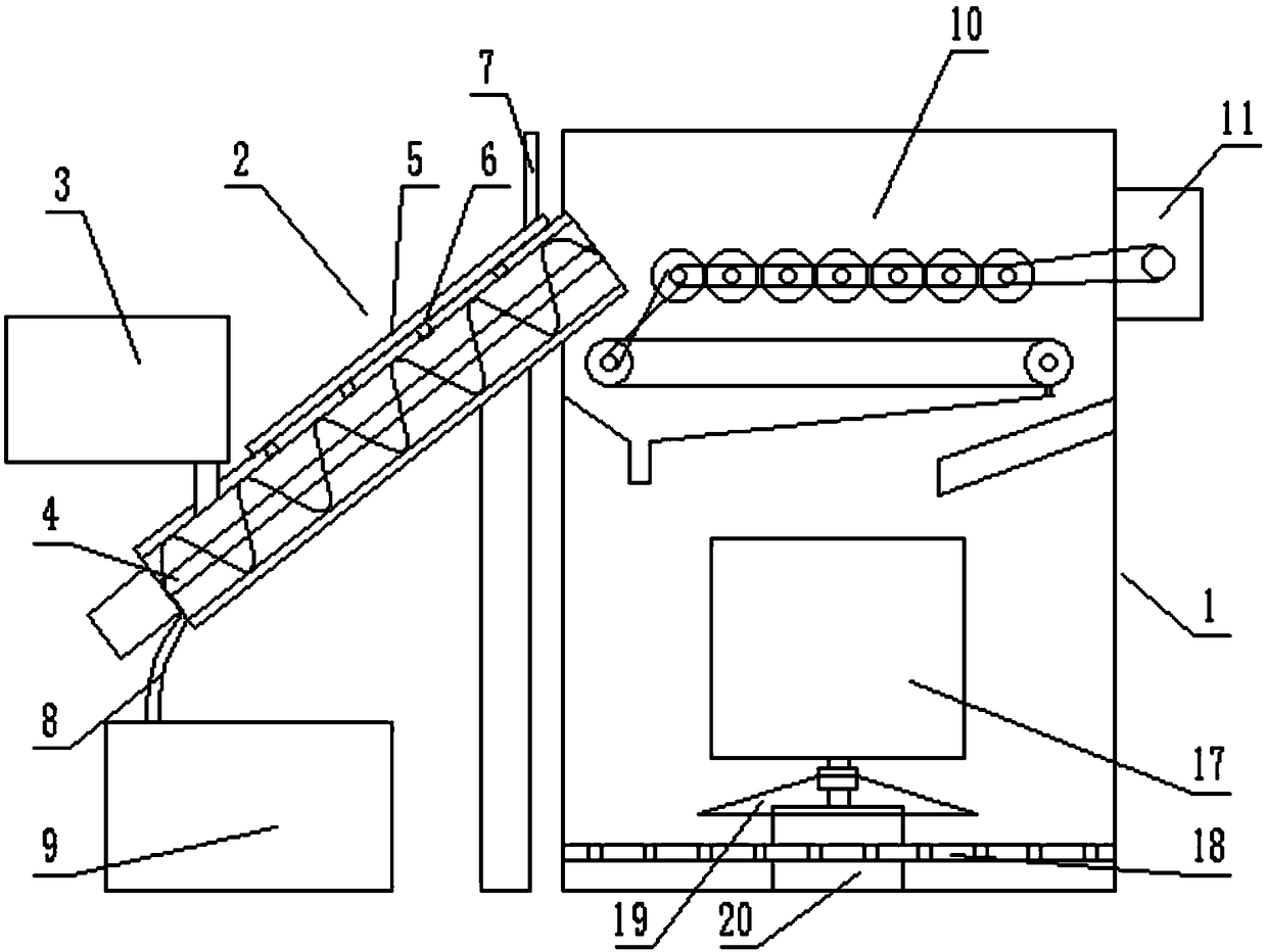
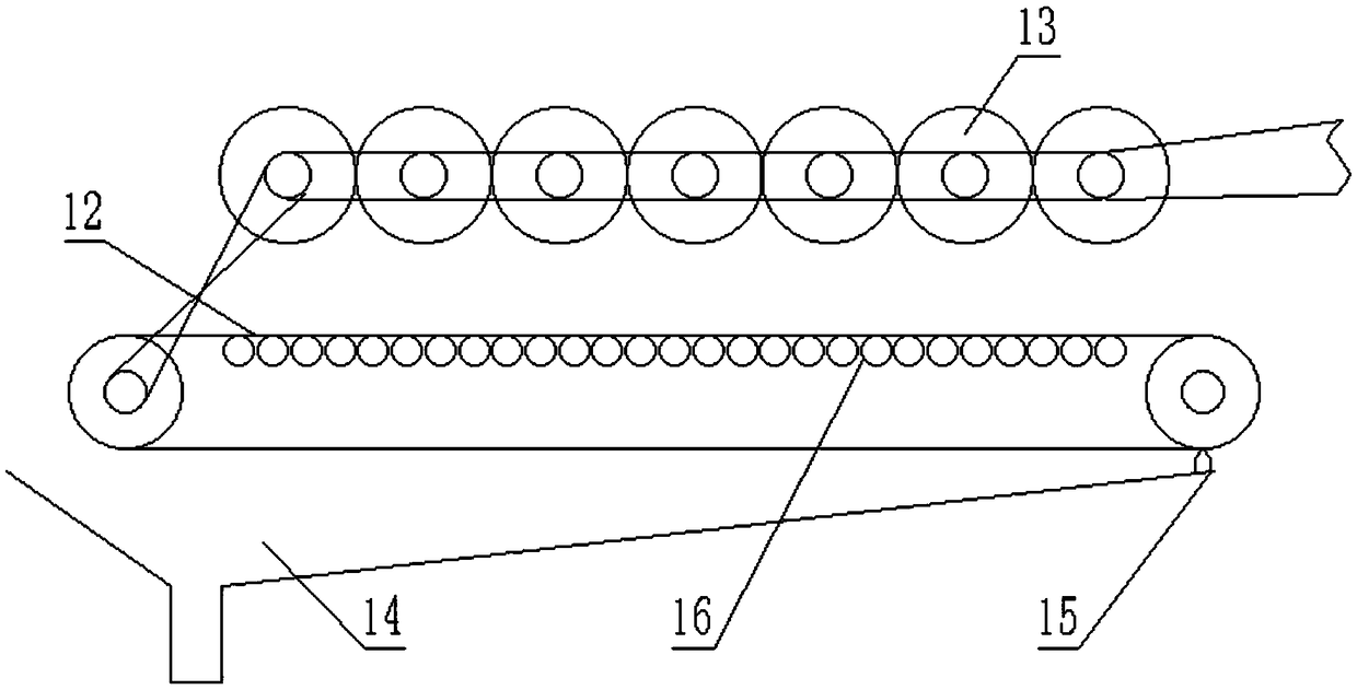
[0022] see Figure 1-3 , a solid-liquid separation treatment device for kitchen waste, comprising a feeder 2 and a dehydration tank 1, the feeder 2 is located on the side of the dehydration tank 1, the feeder 2 has a conveying cylinder arranged obliquely, and feeds The upper end of the device 2 extends into the inside of the dehydration tank 1 and communicates with the inside of the dehydration tank 1, and the lower end of the feeder 2 is connected with a dustbin 3, and the upper part of the dehydration tank 1 is provided with a dehydration conveyor 10, and the dehydration conveyor 10 It includes a conveyor belt 12 arranged in the horizontal direction and a plurality of squeeze rollers 13 arranged side by side above the conveyor belt 12, and the plurality of squeeze rollers 13 are connected by transmission belt transmission, and when one of the squeeze rollers 13 rotates, the remaining squeeze rollers 13 also Rotating in the same direction synchronously, the squeeze roller 13 ...

Embodiment 2

[0029]The difference from Embodiment 1 is that an umbrella cover 19 is also provided in the dehydration box 1, and the umbrella cover 19 is located below the dehydration cylinder 17, and the umbrella cover 19 is in the shape of a circular cone whose diameter gradually increases downwards. After opening the dehydration cylinder 17 and carrying out the discharge of the garbage, the garbage is guided to the dividing plate 18 by the umbrella cover 19, so as to avoid the power chassis 20 from being polluted by the garbage.


PUM


Abstract

The invention discloses a kitchen waste solid-liquid separation treatment device. The kitchen waste solid-liquid separation treatment device comprises a feeder and a dehydration box, the feeder is located on the side face of the dehydration box, the feeder is provided with a conveying cylinder which is obliquely arranged, and the upper end of the feeder extends into the dehydration box and is communicated with the interior of the dehydration box; and a dustbin is connected to the lower end of the feeder, a dehydration conveyor is arranged on the upper part of the interior of the dehydration box, and the dehydration conveyor comprises a conveyor belt arranged in the horizontal direction and a plurality of extrusion rollers arranged above the conveyor belt and in parallel. By arranging the dehydration conveyor composed of the conveyor belt and the multiple extrusion rollers, extrusion dehydration is conducted in the waste conveying process, waste caking is avoided while dehydration is completed, follow-up treatment is facilitated, multiple dehydration on the front end and rear end is conducted through the feeder and the dehydration cylinder, achievement of complete solid-liquid separation of the waste treated by the device is ensured accordingly, and the stink of the waste is greatly reduced.

Description

technical field [0001] The invention relates to environmental protection equipment, in particular to a solid-liquid separation treatment device for kitchen waste. Background technique [0002] With the continuous development of the economy, people's living standards are getting higher and higher, and there are more and more domestic waste, among which kitchen waste occupies a large proportion of domestic waste. The main characteristics of kitchen waste are rich in organic matter, high in water content, perishable, etc. Its properties and odor will have a bad impact on environmental sanitation, and it is easy to breed harmful substances such as pathogenic microorganisms and mycotoxins. extremely serious danger. [0003] Due to the particularity of the dry-wet mixture of kitchen waste, it is very inconvenient to process. In order to facilitate the treatment, dry-wet separation is required. However, the conventional extrusion dewatering method is difficult to guarantee the tre...

Claims


Application Information

Patent Timeline
Patent Type & Authority Applications(China)
IPC IPC(8): B30B9/20B30B15/30
CPCB30B9/20B30B15/30
Inventor 刘会
Owner 苏州驰夫电子科技有限公司
Why Eureka
Try Eureka