
Printing nozzle with temperature adjusting function and printing device

A technology for temperature adjustment and printing nozzles, which is applied in the field of printing nozzles and printing devices. It can solve the problems that the shape of the printing material cannot be obtained, the temperature of the printing head is high, and the nozzle is blocked by the printing material, so as to prevent the high solid content.

Inactive Publication Date: 2018-11-30
TCL CHINA STAR OPTOELECTRONICS TECH CO LTD
View PDF12 Cites 2 Cited by
  • Summary
  • Abstract
  • Description
  • Claims
  • Application Information

AI Technical Summary

Problems solved by technology

In the process of inkjet printing, since the nozzle is continuously printing at high speed, there will be a phenomenon that the temperature of the print head is too high, and the temperature is too high, which will easily cause the solvent in the nozzle to volatilize, thus making the solidity of the printing material As the content increases, the solid content increases, resulting in changes in subsequent drying, baking and other process parameters, resulting in the fact that the required shape of the printing material cannot be actually obtained.
On the other hand, the increase of solid content is very likely to cause the printing material to block the nozzle, so that the printing stops and cannot work

Method used


Image

  • Printing nozzle with temperature adjusting function and printing device
  • Printing nozzle with temperature adjusting function and printing device
  • Printing nozzle with temperature adjusting function and printing device

Examples


Embodiment 1

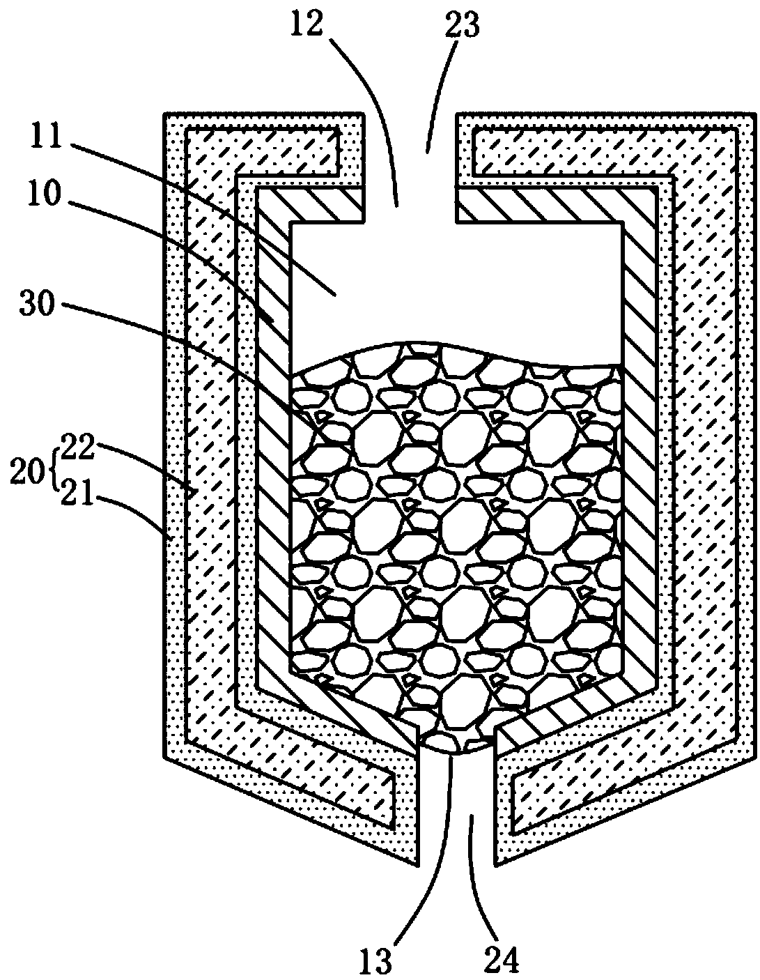
[0023] like figure 1 As shown, the print head with temperature adjustment function according to this embodiment includes a head body 10 and a temperature adjustment layer 20, the head body 10 has a chamber 11, the chamber 11 is used to load printing materials 30, and the temperature adjustment layer 20 is arranged on the head On the main body 10 , the temperature regulating layer 20 is used for regulating the temperature of the shower head main body 10 . In this way, during the printing process, when the temperature of the shower head body 10 rises, the temperature adjustment layer 20 absorbs the heat of the shower head body 10 to reduce the temperature of the shower head body 10, so as to prevent the high temperature shower head body 10 from evaporating the solvent in the printing material 30 , to ensure the stability of the solid content in the printing material 30 and to ensure the stability of the printing process.

[0024] Specifically, as a preferred embodiment, the tem...

Embodiment 2

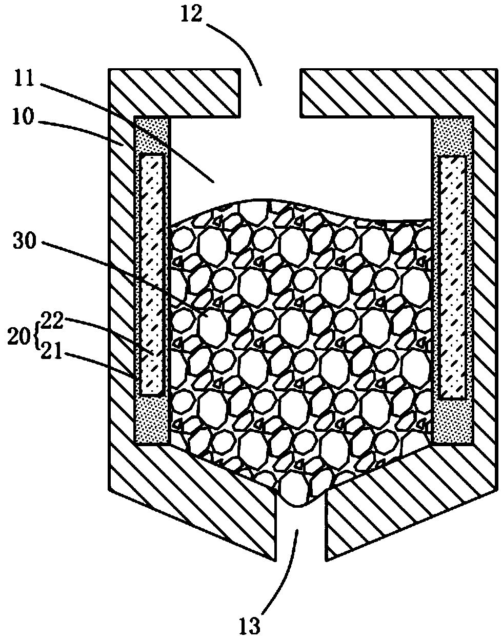
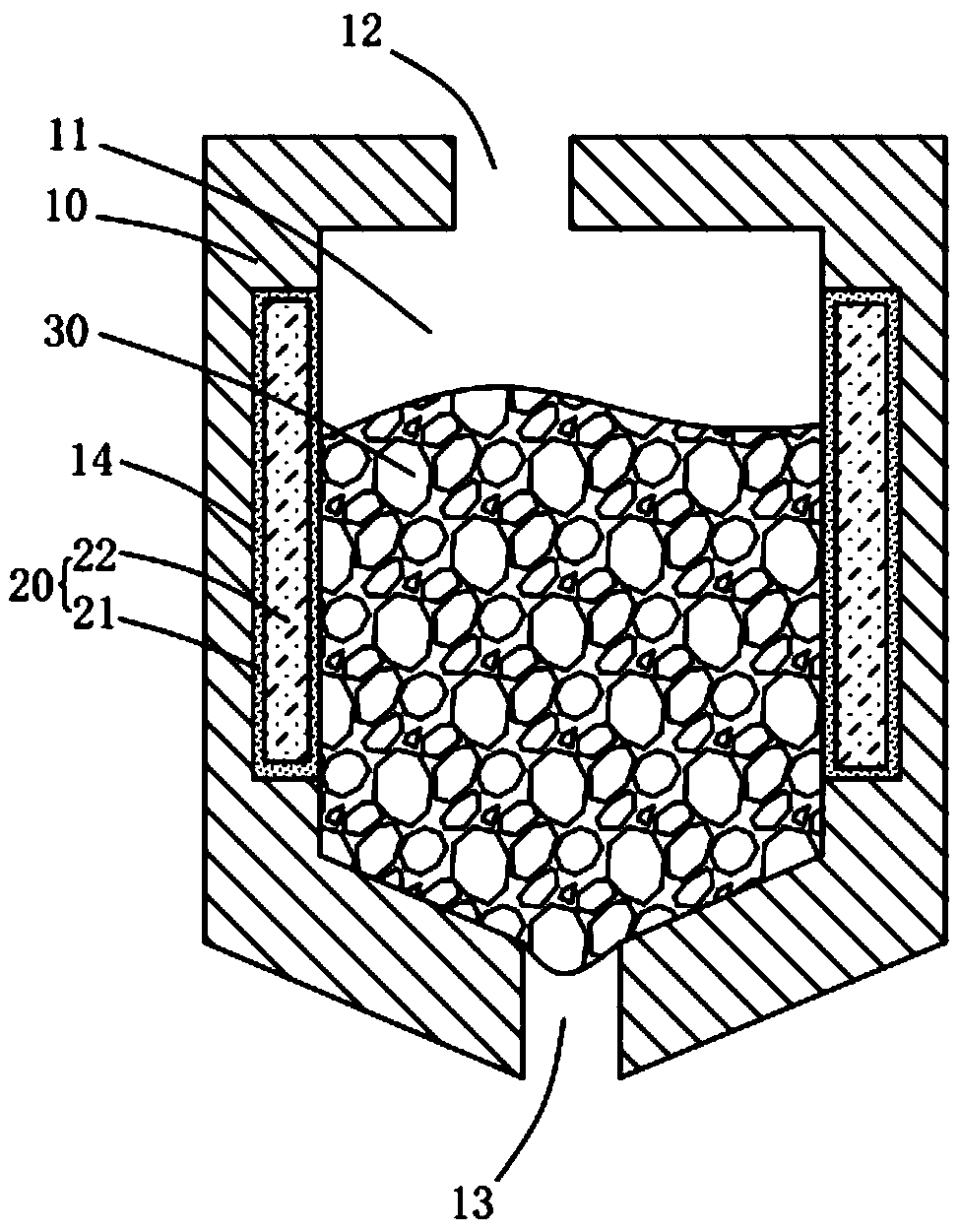
[0031] like Figure 2A As shown, the difference between the printing head in the second embodiment and the printing head in the first embodiment is that the temperature regulating layer 20 in the second embodiment is arranged inside the cavity 11 .

[0032] Specifically, the protective layer 21 of the temperature regulation layer 20 is adhered to the inner wall surface of the accommodating chamber 11 . The shape of the protective layer 21 matches the shape of the inner wall of the accommodating chamber 11 , and the protective layer 21 is fixed on the inner wall by glue. In order to facilitate the installation or removal of the temperature regulating layer 20, the inlet hole 12 of the shower head body 10 should be as large as possible.

[0033] As a preferred embodiment, the protective layer 21 is crimped to form a cylindrical structure, so that when the temperature regulation layer 20 is placed in the accommodating chamber, the protective layer 21 can be closely attached to t...

Embodiment 3

[0037] like image 3 As shown, the printing device according to the third embodiment of the present invention includes the ink supply pipeline 40, the nozzle 50 and the print nozzle with temperature adjustment function in the first or second embodiment, wherein the ink supply pipeline 40 and the nozzle 50 are respectively communicated and accommodated Cavity 11.

[0038] Specifically, the ink supply pipe 40 communicates with the inlet hole 12 , and the nozzle 50 communicates with the outlet hole 13 . Wherein, the number of nozzles 50 may be multiple, and multiple nozzles 50 communicate with the chamber 11 of the same printhead body 10 at the same time, and precise spraying can be realized by controlling the inkjet state of each nozzle 50 .

[0039] In the printing device disclosed in this embodiment, a temperature regulating layer is provided on the nozzle body. During the rapid printing process, when the temperature of the nozzle body rises too fast, the temperature regulati...


PUM


Abstract

The invention discloses a printing nozzle with a temperature adjusting function and a printing device. The printing nozzle comprises a nozzle main body and a temperature adjusting layer, wherein the nozzle main body is provided with an accommodating cavity; the accommodating cavity is used for loading printing materials; the temperature adjusting layer is arranged on the nozzle main body; and thetemperature adjusting layer is used for adjusting the temperature of the nozzle main body. The printing device comprises an ink supply channel, a jet and the printing nozzle with the temperature adjusting function, wherein the ink supply channel and the jet communicate with the accommodating cavity. According to the printing nozzle with the temperature adjusting function and the printing device, the temperature adjusting layer is arranged on the nozzle main body, when the temperature of the nozzle main body rises too fast during the quick printing process, the temperature adjusting layer absorbs heat to decrease the temperature of the nozzle main body, printing equipment is prevented from being damaged due to high temperature, and the phenomenon that holes are blocked as the solid contentof the printing materials is relatively high is prevented.

Description

technical field [0001] The invention relates to the field of inkjet printing equipment, more specifically, to a printing nozzle and a printing device with a temperature regulating function. Background technique [0002] In the current field of lighting and display, organic light-emitting diodes (Organic Light-Emitting Diode, OLED) have many advantages, such as low start-up voltage, light and thin, self-illumination, etc., more and more researched and widely used Develop lighting products and panel industries to meet the needs of low energy consumption, thinness and surface light sources. [0003] At present, the inkjet printing process will be designed in the production process of OLED. In the process of inkjet printing, since the nozzle is continuously printing at high speed, there will be a phenomenon that the temperature of the print head is too high, and the temperature is too high, which will easily cause the solvent in the nozzle to volatilize, thus making the solidit...

Claims


Application Information

Patent Timeline
Patent Type & Authority Applications(China)
IPC IPC(8): B41J2/01B41J2/135B41J2/165H01L51/00H10K99/00
CPCB41J2/01B41J2/135B41J2/1408B41J2/165H10K71/135B41J2/16502
Inventor 黄辉邓联谱
Owner TCL CHINA STAR OPTOELECTRONICS TECH CO LTD
Learn More