
Underwater environment monitoring system based on ROV

An environmental monitoring system, monitoring system technology, applied in the direction of testing water, material inspection products, etc., can solve the problems of high installation and maintenance costs, difficult wiring, difficult to dismantle, etc., to save monitoring costs, improve monitoring efficiency, and improve monitoring range effect

Inactive Publication Date: 2018-11-30
HAINAN UNIVERSITY
View PDF7 Cites 8 Cited by
  • Summary
  • Abstract
  • Description
  • Claims
  • Application Information

AI Technical Summary

Problems solved by technology

For a piece of water, it needs to be released on a large scale, the installation is complicated, the wiring is difficult, the exposed water surface affects people's production activities, and its installation cost and maintenance cost are relatively high
This kind of monitoring system has a single application scenario, and it cannot be used in remote waters without power facilities, and it is not easy to dismantle after being fixed, so it is not suitable for sampling and monitoring in multiple waters
[0003] On the other hand, the price of water quality monitoring equipment currently on the market ranges from a few thousand yuan to more than a hundred thousand yuan depending on the difference in performance. The equipment with lower prices often has fewer functions and performance is difficult to guarantee; the monitoring equipment with relatively complete functions and better user experience Equipment is more expensive
On the other hand, most of the existing water quality monitoring equipment does not have the function of forecasting and alarming, and cannot predict the development trend of water conditions.

Method used


Image

  • Underwater environment monitoring system based on ROV
  • Underwater environment monitoring system based on ROV
  • Underwater environment monitoring system based on ROV

Examples


Embodiment Construction

[0030] The principles and features of the present invention will be described below with reference to the accompanying drawings. The listed embodiments are only used to explain the present invention, and are not used to limit the scope of the present invention.

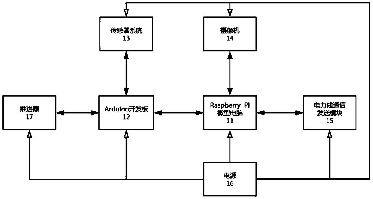
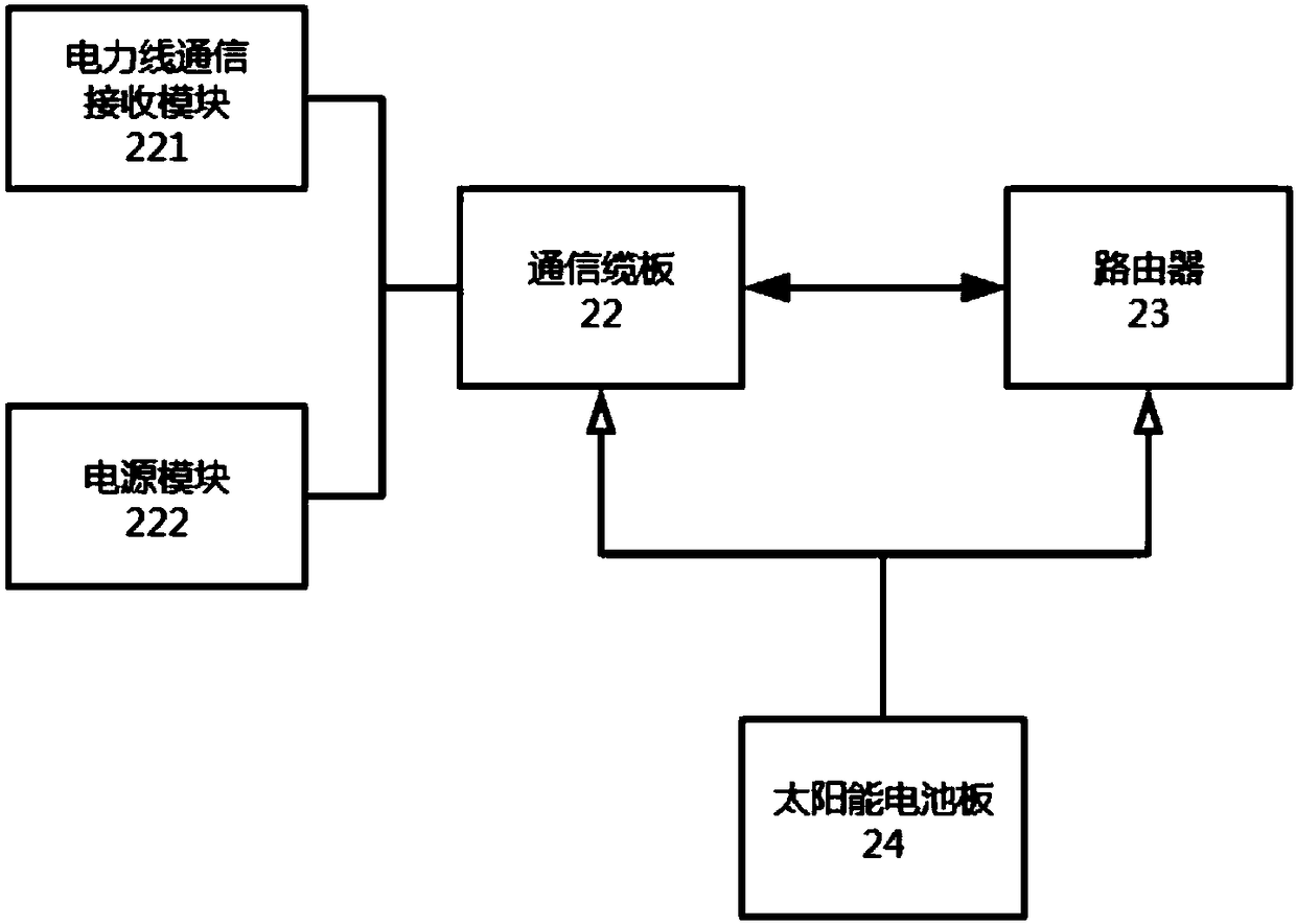
[0031] Reference figure 1 , The present invention provides an ROV-based underwater environment monitoring system. The underwater environment monitoring system includes an ROV underwater operation platform 1, a surface data forwarding terminal 2, and an upper computer monitoring system 3. The ROV underwater operation platform 1 A power line communication sending module 15 is provided, and the water surface data forwarding terminal 2 is provided with a power line communication receiving module 25. The power line communication sending module 15 and the power line communication receiving module 25 are connected by a zero-buoyancy cable for data interaction; the water surface data The forwarding end 2 is simultaneously connect...


PUM


Abstract

The invention discloses an underwater environment monitoring system based on an ROV. The underwater environment monitoring system comprises an ROV underwater working platform, a water surface data forwarding end and a host computer monitoring system. The ROV underwater working platform is provided with a power line communication transmitting module; the water surface data forwarding end is provided with a power line communication receiving module; the power line communication transmitting module and the power line communication receiving module are connected by a zero buoyancy cable; the watersurface data forwarding end is connected with the host computer monitoring system through a wireless network; the ROV underwater working platform is used for monitoring a water area environment and processing acquired data in virtue of a Raspberry Pi microcomputer and an Arduino development board; the surface data forwarding end is used to forwarding the data acquired by the ROV underwater working platform to the host computer monitoring system; and the host computer monitoring system is used for monitoring the acquired data in real time, remotely controlling the ROV underwater working platform and performing statistics and analysis on water area environment data. The system makes up for the shortcomings of traditional monitoring, and has the advantages of a wide application scope, good expansibility, three-dimensional layered monitoring, high degree of automation, low cost and the like.

Description

Technical field [0001] The invention relates to the technical field of water environment monitoring, in particular to an ROV-based underwater environment monitoring system. Background technique [0002] The existing water area monitoring equipment mainly includes traditional water area monitoring equipment and fixed-point environmental monitoring system equipment. Traditional water area monitoring equipment often relies on manual entry into the water area to collect water samples and then to the shore for analysis and testing, that is, manual monitoring. The fixed-point environmental monitoring system equipment achieves real-time performance on the basis of traditional water area monitoring technology, but the monitoring range is fixed, and the monitoring area is limited, and it can only monitor one point in the three-dimensional space. For a piece of water, large-scale deployment is required, installation is complicated, wiring is difficult, and the exposed water surface affects...

Claims


Application Information

Patent Timeline
Patent Type & Authority Applications(China)
IPC IPC(8): G01N33/18
CPCG01N33/18
Inventor 曹春杰程大果高昌正马鹏程龚胜林彬宋颜均
Owner HAINAN UNIVERSITY
Learn More