Antenna pedestal for airport surface detection radar

A technology for monitoring radar and airport scenes, applied to radio wave measurement systems, instruments, etc., can solve the problems of reduced shaft strength, low transmission efficiency, and complex antenna base structure, etc., to reduce dynamic unbalanced couples and work stably Guaranteed performance and the effect of eliminating eccentricity

Active Publication Date: 2018-11-30
ANHUI SUN CREATE ELECTRONICS
View PDF5 Cites 5 Cited by
  • Summary
  • Abstract
  • Description
  • Claims
  • Application Information

AI Technical Summary

Problems solved by technology

The disadvantages of the above-mentioned traditional methods are as follows: First, due to the use of multi-stage gear transmission, the transmission efficiency is low and the reduction ratio is large, resulting in a very small rotational speed of the antenna.
The radar antenna itself has a very large wind surface, which causes the antenna to transmit the wind force to the transmission shaft and even the motor shaft in the antenna base, and then the motor is overloaded or even shut down, which greatly affects the actual use
Finally, the traditional antenna base includes a series of structures such as a turntable, a slewing ring, a pinion, a clutch, a reducer, and a motor, and each structure is usually arranged in sequence along the vertical direction, which not only leads to the complexity and bulkiness of the antenna base structure. At the same time, a large number of key connection structures are used between the internal shaft and the shaft, which leads to a sharp decrease in the strength of the shaft body itself, and finally brings hidden dangers to the normal and stable operation of the radar antenna.

Method used


Image

  • Antenna pedestal for airport surface detection radar
  • Antenna pedestal for airport surface detection radar
  • Antenna pedestal for airport surface detection radar

Examples


Embodiment Construction

[0038] For ease of understanding, combined here Figure 1-12 , the concrete structure and working mode of the present invention are further described as follows:

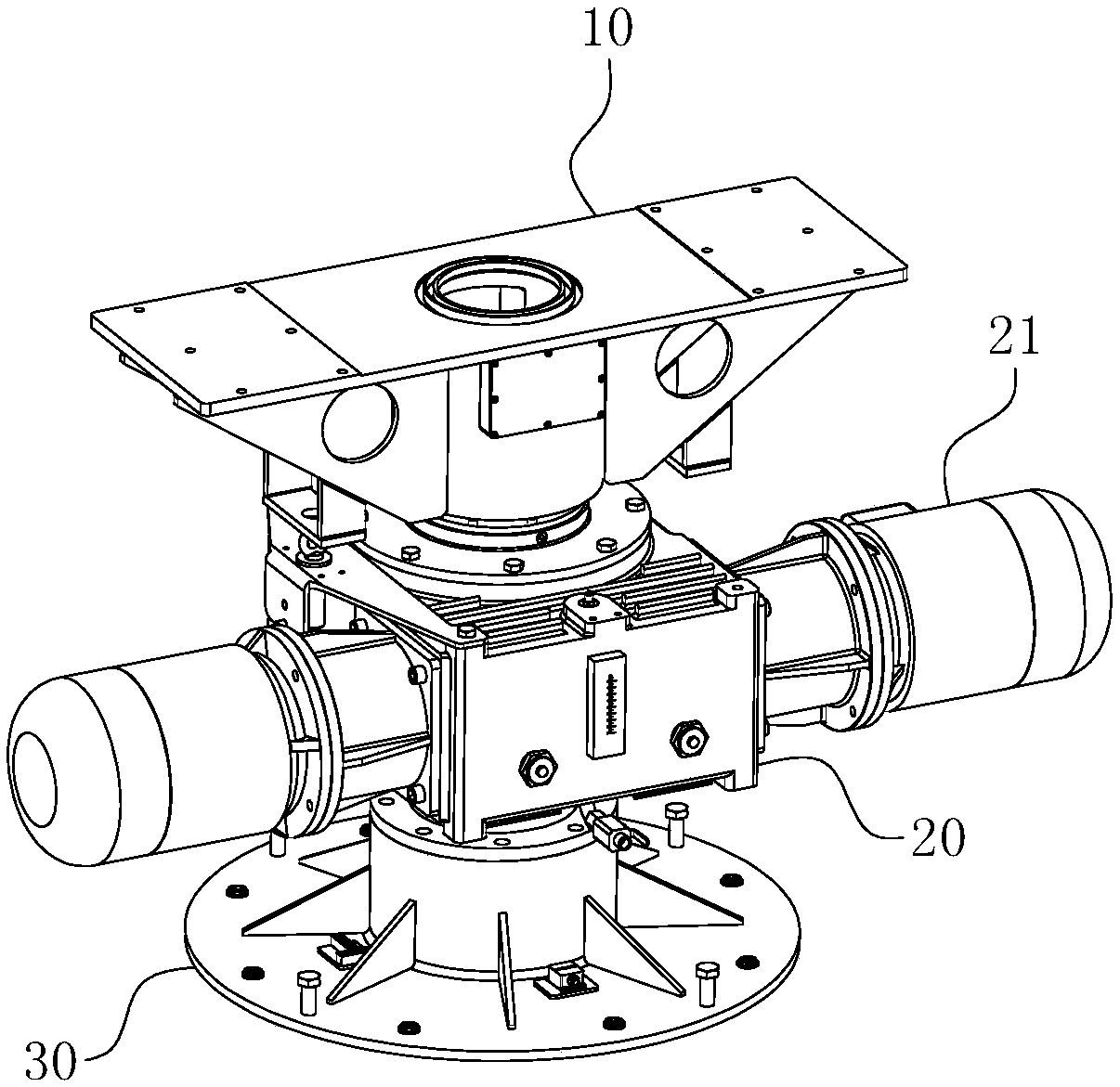
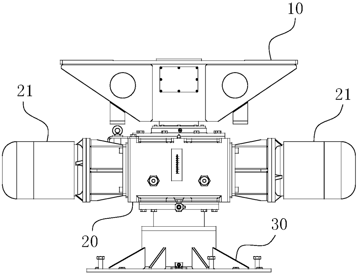
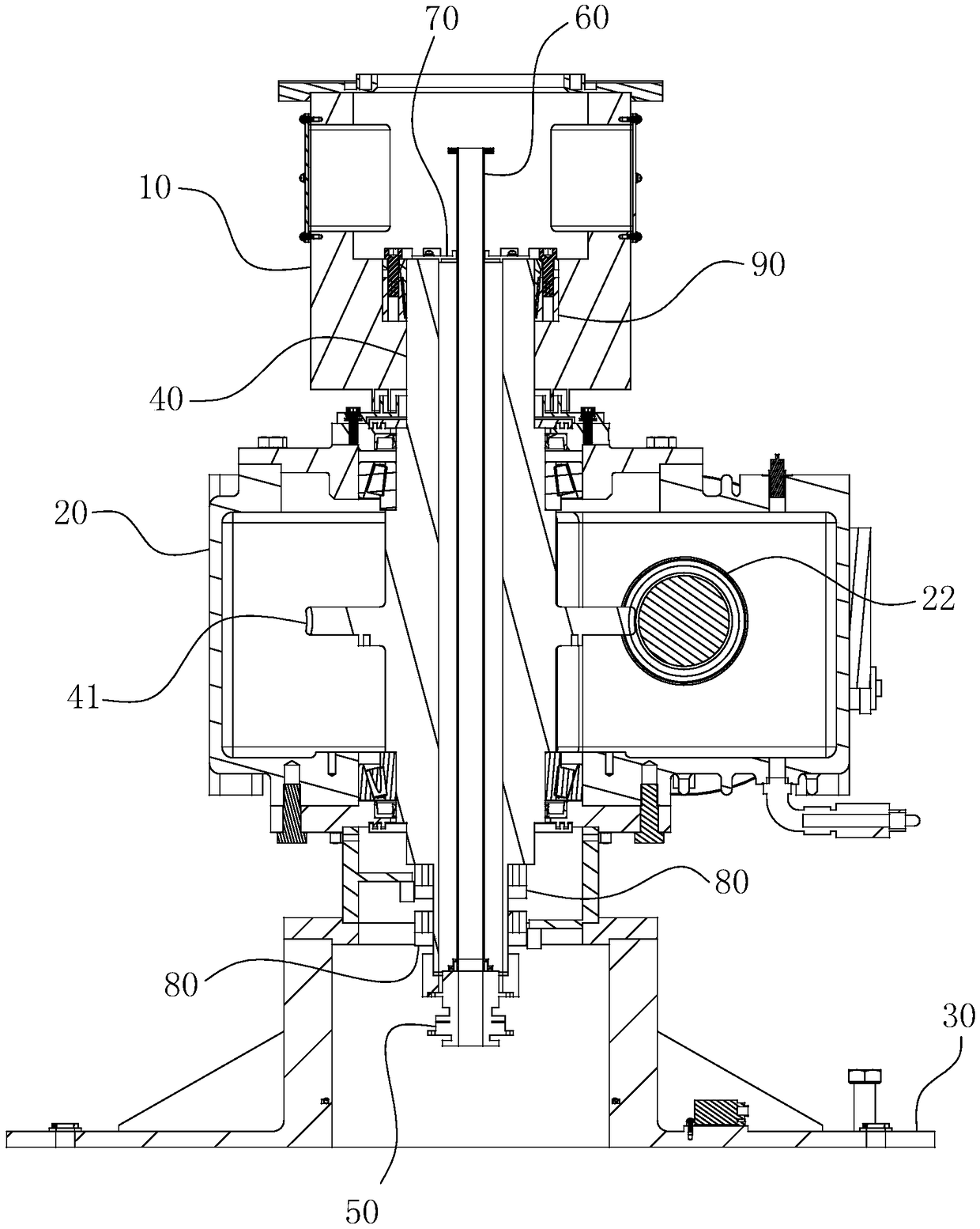
[0039] The specific structure of the present invention is as Figure 1-12 As shown, its main structure includes a power motor 21 , an encoder 80 , a rotating support 50 , a rotating waveguide 60 , a waveguide fixing plate 70 , an expansion ring 90 , an antenna support 10 and a base 30 . The power motor 21 is a hollow output shaft speed reducer driven by double motors, and is installed on one side of the power box 20 . The antenna support 10 is connected to the hollow rotational shaft 40 via the expansion ring 90 . The rotating waveguide 60 passes through the rotating shaft 40 , the upper end passes through the waveguide fixing plate 70 so as to be fixedly connected to the top surface of the rotating shaft 40 , and the lower end of the waveguide is connected to the turning surface of the rotating support 50 . Both...


PUM


Abstract

The invention belongs to the technical field of airport surface detection radars, and particularly relates to an antenna pedestal for the airport surface detection radar. The antenna pedestal comprises an antenna support, a power box, a base and a rotating shaft, wherein a rotating support is arranged on the base; the antenna pedestal further comprises an encoder; the top end of the rotating shaftcoaxially penetrates into a small-aperture section of a mounting hole of the antenna support from bottom to top, and a hole-shaft inserting fit is formed between the rotating shaft and the mounting hole; the antenna pedestal further comprises an expansion ring; when a rotary screw of the expansion ring generates a rotary action, an inner expansion ring and an outer expansion ring generate radialexpansion due to conical fit, and interference fit is formed between the inner expansion ring and the rotating shaft and between the outer expansion ring and the mounting hole. The antenna pedestal issmall and exquisite in size, simple in structure and capable of ensuring normal operation of a radar antenna at the rotation speed of 60 revolutions per minute and even higher, and the high transmission efficiency, the operation stability and the high service life can be guaranteed synchronously.

Description

technical field [0001] The invention belongs to the technical field of airport surface surveillance radars, and in particular relates to an antenna base for airport surface surveillance radars that supports and drives the antennas of airport surface surveillance radars to rotate at high speed. Background technique [0002] The radar antenna base is used to carry the radar antenna. It is the basis for the rotation of the radar antenna and an essential part of the radar system. The traditional radar antenna seat includes a base, a turntable, a slewing bearing, a pinion, a clutch, a speed reducer and a motor are arranged on the base, and a radar antenna is set up on the turntable. Among them, the motor and the reducer are fixed at the bottom of the base. The output shaft of the reducer goes deep into the base from bottom to top and connects with the clutch in the base. The turntables mesh with each other. When working, the motor drives the clutch and the pinion gear by drivin...

Claims


Application Information

Patent Timeline
Patent Type & Authority Applications(China)
IPC IPC(8): G01S7/03
CPCG01S7/032
Inventor 周雷丁飞张伟
Owner ANHUI SUN CREATE ELECTRONICS
Why Eureka
Try Eureka