Supercharge Your Innovation With Domain-Expert AI Agents!

Voltage following filtering circuit

A technology of filter circuit and follower circuit, applied in the field of power follower filter circuit, can solve the problems of high cost, ineffectiveness of low-frequency ripple noise, cut off the effective DC component of power supply, etc., and achieve the effect of reducing power consumption

Active Publication Date: 2018-11-30
深圳市钜微电子技术有限公司
View PDF4 Cites 4 Cited by
  • Summary
  • Abstract
  • Description
  • Claims
  • Application Information

AI Technical Summary

Problems solved by technology

[0009] Among the filtering methods of Scheme 1 and Scheme 2 above, Scheme 1 can only filter out ripple noise, but for low-frequency ripple noise, the cost is too high, or even invalid
Solution 2 is effective for ripple noise, but it will cut off the effective DC component of the power supply. It is especially not suitable for scenarios where Vin is not fixed, and it will cause a lot of loss

Method used


Image

  • Voltage following filtering circuit
  • Voltage following filtering circuit
  • Voltage following filtering circuit

Examples


Embodiment 1

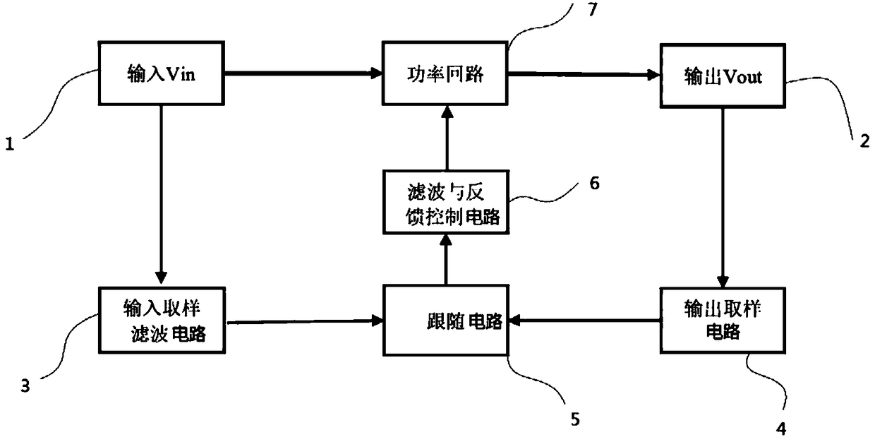
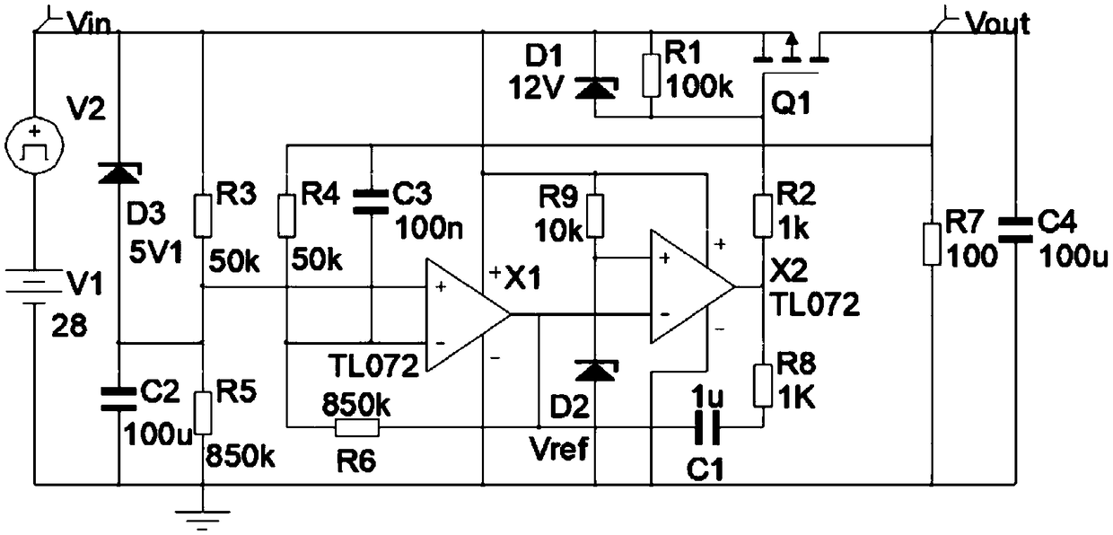
[0034] Such as figure 2 As shown, the basic implementation scheme of the present invention is a differential active follower filter, and the circuit is as figure 2 As shown, V1 and V2 form "input sampling Vin", resistor R3, resistor R5, and capacitor C2 form input sampling filter circuit 3, resistor R4, capacitor C3, and resistor R6 form output sampling circuit 4, and the output of operational amplifier X1 will follow the input The difference between output and input sampling filter circuit 3 and output sampling circuit 4 is used as follower circuit 5 and output to operational amplifier X2. Resistor R9 and Zener diode D2 are reference sources. Resistor R9, Zener diode D2 and operational amplifier X2, resistor R8 and capacitor C1 form a filtering and feedback control circuit 6 . The operational amplifier X2 adjusts the output of the operational amplifier X2 according to the output of the operational amplifier X1 and the reference source Vref, and controls the working state o...

Embodiment 2

[0051] Such as Figure 4 As shown, on the basis of the first embodiment, the follower circuit 5 and the filter and feedback control circuit 6 are composed of a follower, filter and feedback control unit, and the follower, filter and feedback control unit includes an operational amplifier X1 and a resistor R2, The power loop 7 includes a MOS transistor Q1, the positive input terminal of the operational amplifier X1 is connected to the output terminal of the output sampling circuit 2, and the negative input terminal of the operational amplifier X1 is connected to the output of the input sampling filter circuit 1 The output terminal of the operational amplifier X1 is connected to the gate of the MOS transistor Q1 through the resistor R2, the source of the MOS transistor Q1 is connected to the voltage input terminal 1, and the drain of the MOS transistor Q1 Pole connected to the voltage output terminal 2, the operational amplifier X1 adjusts its own output according to the differe...

Embodiment 3

[0073] Such as Image 6 , 7 As shown, on the basis of Embodiment 1, a Zener diode D3 is added, specifically, the power supply follower filter circuit 6 further includes a Zener diode D3, and the anode of the Zener diode D3 is connected to the capacitor C2 and then grounded. The cathode of the Zener diode D3 is connected between the voltage input terminal 1 and the power loop 7 .

[0074] Zener diode D3 is to improve the response speed of the filter circuit when switching on and off. In addition, in some specific scenarios, in order to further improve the response speed of switching on and off of the active filter and the response speed of short-circuit protection, diode D4 will be added, such as Image 6 , 7 shown.

[0075] The power loop 7 can use a P-MOSFET tube, an N-MOSFET tube, or a triode as the main device of the power loop. In the present invention, the diode D1 is used for protection of the power loop.

[0076] A power supply following filter circuit provided by t...


PUM


Abstract

The invention provides a voltage following filtering circuit. The voltage following filtering circuit comprises an input sampling filtering circuit, an output sampling circuit, a following circuit, afiltering and feedback control circuit and a power loop, wherein the input sampling filtering circuit is connected with a voltage input end, the output sampling circuit is connected with a voltage output end, the voltage input end is connected with the voltage output end by the power loop, an output end of the input sampling filtering circuit and an output end of the output sampling circuit are connected with an input end of the following circuit, and an output end of the following circuit is connected with an input end of the filtering and feedback control circuit. The voltage following filtering circuit has the beneficial effects that the change of an input power supply can be followed, effective DC constituent of power supply is effectively maintained, the voltage following filtering circuit can be widely applied to power supply filtering loops having various voltages and particularly can be applied to a circuit of which an output voltage is needed to adjust, ripple and noise are only filtered, the DC constituent of the power supply is completely maintained, the power consumption of a filter is reduced, and energy saving and emission reduction are achieved.

Description

technical field [0001] The invention relates to a filter circuit, in particular to a power supply following filter circuit. Background technique [0002] Some DC power supply equipment is very sensitive to the ripple noise of the DC input Vin. Therefore, it is necessary to filter the power supply to filter out the AC components of the ripple noise to obtain the expected DC components. [0003] At present, the traditional solution is mainly to use the switching power supply or the linear power supply rectified by the transformer to supply power to the rear stage, and the following solutions are generally used: [0004] Scheme 1: Passive filter circuit: LC filter composed of capacitor C filter or inductor L+capacitor C, the principle is as follows, the input power Vin passes through L1 and C1 to obtain Vout1. [0005] Solution 2: Low dropout linear regulator LDO (low dropout regulator) active filter circuit uses a three-terminal regulator to obtain a fixed DC output. The prin...

Claims


Application Information

Patent Timeline
Patent Type & Authority Applications(China)
IPC IPC(8): H02M1/14
CPCH02M1/14H02M1/143
Inventor 奚志敏唐志杰
Owner 深圳市钜微电子技术有限公司
Features
  • R&D
  • Intellectual Property
  • Life Sciences
  • Materials
  • Tech Scout
  • Unparalleled Data Quality
  • Higher Quality Content
  • 60% Fewer Hallucinations
Learn More