
Site selection method for monitoring stations and device for site selection of monitoring stations

A technology of monitoring stations and stations, which is applied in the field of communication, can solve problems such as the distribution of difficult monitoring stations, and achieve the effects of shortening the fault duration, wide applicability, and improving maintenance efficiency

Active Publication Date: 2018-11-30
GUANGXUN SCI & TECH WUHAN
View PDF7 Cites 4 Cited by
  • Summary
  • Abstract
  • Description
  • Claims
  • Application Information

AI Technical Summary

Problems solved by technology

[0006] The technical problem to be solved by the embodiments of the present invention is that the monitoring station is the core function site of the optical cable monitoring system, and the site selection of the monitoring station directly affects the range of optical cables that the optical cable monitoring system can monitor. Due to the increase in the complexity of the optical fiber network, the number of relay sites The more, for hundreds or even thousands of relay stations, how to reasonably select the optimal monitoring station, it is difficult to complete the distribution of monitoring stations by manual means

Method used


Image

  • Site selection method for monitoring stations and device for site selection of monitoring stations
  • Site selection method for monitoring stations and device for site selection of monitoring stations
  • Site selection method for monitoring stations and device for site selection of monitoring stations

Examples


Embodiment 1

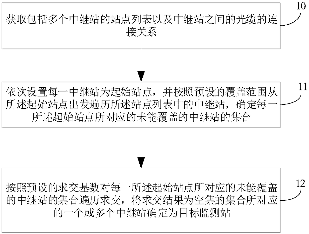
[0047]Embodiment 1 of the present invention provides a site selection method for a monitoring station. The site selection method for a monitoring station is applicable to optical fiber networks with various network connection relationships, especially in scenarios where the connection relationship of optical fiber networks is complex and there are many relay stations. The site selection method of the monitoring station in this embodiment 1 can quickly and effectively select the optimal monitoring site from many relay stations, and improve site selection efficiency. The site selection method for the monitoring station includes the following steps:

[0048] Step 10: Obtain a site list including multiple relay stations and connection relationships of optical cables between the relay stations.

[0049] In this embodiment, when selecting the location of the monitoring station, it is first necessary to obtain the actual optical cable distribution diagram, and then select a suitable ...

Embodiment 2

[0097] see Figure 5 , Figure 5 It is a schematic structural diagram of a device for site selection of a monitoring station provided by an embodiment of the present invention. The device for address selection of a monitoring station in this embodiment includes one or more processors 51 and a memory 52 . in, Figure 5 A processor 51 is taken as an example.

[0098] Processor 51 and memory 52 can be connected by bus or other means, Figure 5 Take connection via bus as an example.

[0099] The memory 52, as a non-volatile computer-readable storage medium based on the location selection method of the monitoring station, can be used to store non-volatile software programs, non-volatile computer-executable programs and modules, such as in Embodiment 1 Based on the siting method of the monitoring station and the corresponding program instructions. The processor 51 executes various functional applications and data processing of the site selection method of the monitoring statio...


PUM


Abstract

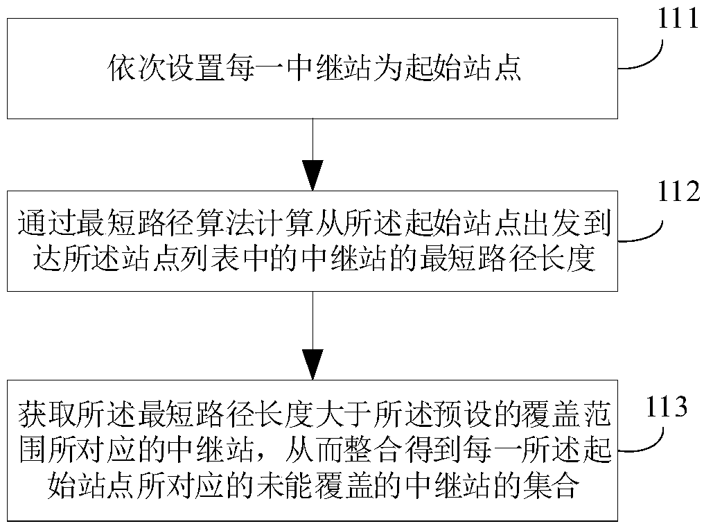
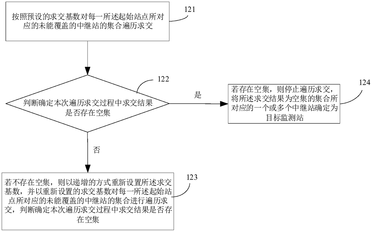
The invention relates to the technical field of communication and provides a site selection method for monitoring stations and a device for site selection of the monitoring stations. The site selection method for the monitoring station comprises the steps of obtaining a station list comprising a plurality of relay stations and a connection relationship of optical cables among the relay stations; setting each relay station as a start station in sequence, traversing the relay stations in the station list starting from the start station according to a preset coverage range, and determining a setof the uncovered relay stations corresponding to each start station; and carrying out traversal and intersection on the set of the uncovered relay stations corresponding to each start station according to a preset intersection base number, and determining one or more relay stations corresponding to the sets of which intersection result is a null set as target monitoring stations. According to thesite selection method for the monitoring station provided by the invention, the site selection efficiency and accuracy of the monitoring stations is improved, and the method and the device have relatively wide applicability.

Description

【Technical field】 [0001] The invention relates to the field of communication technology, in particular to a method for selecting a site for a monitoring station and a device for site selection for a monitoring station. 【Background technique】 [0002] With the development of the communication network, the optical fiber network becomes more and more complex, and due to the influence of engineering construction and natural disasters, there are more and more faults in the optical fiber network. The optical cable monitoring system can monitor the optical fiber in real time, automatically find the faults and hidden dangers of the optical cable, shorten the fault duration of the optical cable, improve the maintenance efficiency of the transmission network, and reduce the maintenance cost of the line. [0003] When designing the optical cable monitoring system scheme, since the monitoring station is the core function site of the optical cable monitoring system, the distribution of t...

Claims


Application Information

Patent Timeline
IPC IPC(8): H04B10/071H04B10/079H04L12/721H04Q11/00
CPCH04B10/071H04B10/0791H04L45/123H04Q11/0005H04B10/0773H04Q11/0062H04Q2011/0083
Inventor 余磊陈星云杨易之杨明易水寒周治柱
Owner GUANGXUN SCI & TECH WUHAN
Learn More