Novel intelligent CT machine
An intelligent and new technology, applied in medical science, patient positioning for diagnosis, radiological diagnostic equipment control, etc., can solve the problems of lack of practical functions for medical personnel's diagnosis and observation, poor display effect, and incapable of scanning and imaging inspection, etc. , to achieve the effect of convenient observation and diagnosis, good display effect and increased comfort
- Summary
- Abstract
- Description
- Claims
- Application Information
AI Technical Summary
Problems solved by technology
Method used
Image
Examples
Embodiment 1
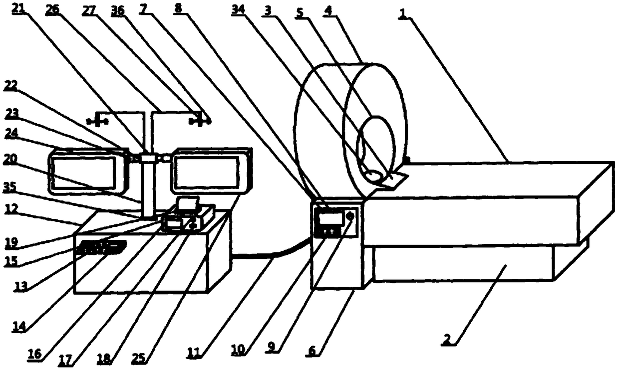
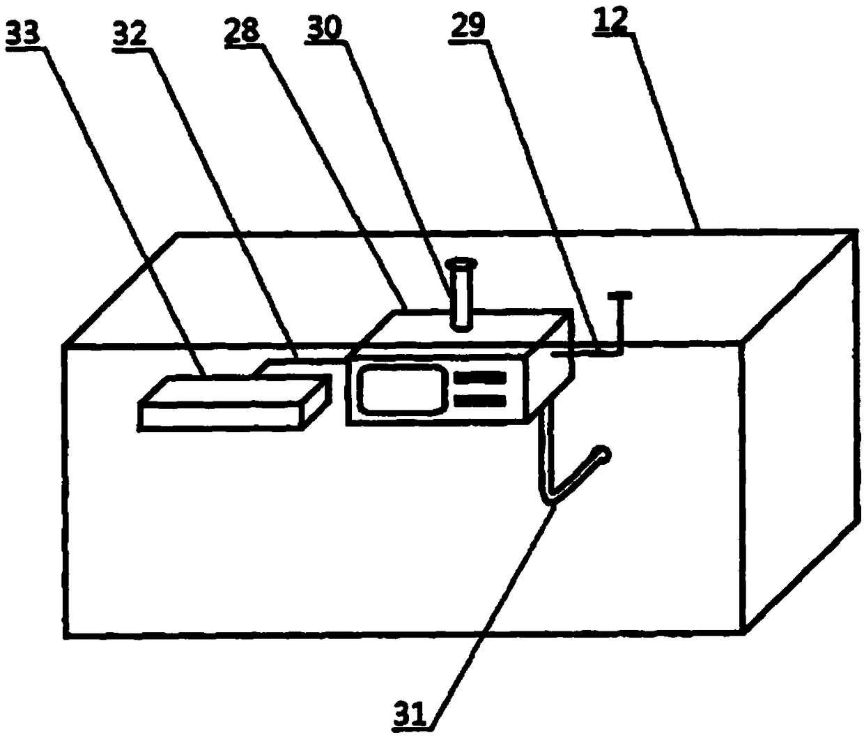
[0025] Such as Figure 1-4 A new type of intelligent CT machine shown is characterized in that it includes an inspection bed 1, a bed base 2 is arranged on the lower side of the inspection bed 1, a neck connection layer 3 is arranged on the left side of the inspection bed 1, and a neck connection layer 3 is arranged on the left side of the inspection bed 1. The left side of the connection layer 3 is provided with a CT inspector 4, the right side of the CT inspector 4 is provided with a scanning inspection port 5, the lower side of the CT inspector 4 is provided with an inspector base 6, and the front side of the inspector base 6 is provided with an inspection control Board 7, a display screen 8 is arranged on the front side of the inspection control board 7, a power button 9 is arranged on the right side of the display screen 8, a button control board 10 is arranged on the lower side of the display screen 8, and a connecting conduit is arranged on the left side of the inspector...
Embodiment 2
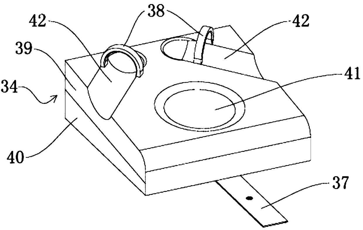
[0030] Such as Figure 1-4 Shown, embodiment 2 is improved on the basis of embodiment 1. The upper surface of the headrest part is provided with a headrest groove 41 into which a person's head can rest, and the wrist buckle 38 is located above the headrest groove 41; The arm groove 42 extending to the position of the wrist buckle 38, the wrist buckle 38 is two left and right above the headrest groove 41, and the arm groove 42 is two extending from the left and right sides to the left and right wrist buckle 38 respectively. indivual. The headrest part includes upper and lower layers, the top layer is a soft layer 39 , and the bottom layer is a plastic board layer 40 . The headrest groove 41 can adapt to the patient's head, making the patient more comfortable after lying down.
[0031] The rest of the structure and working principle of embodiment 2 are the same as embodiment 1.
Embodiment 3
[0033] Such as Figure 1-4Shown, embodiment 3 is improved on the basis of embodiment 1. The wrist buckle 38 is a semi-circular structure, which is rotatably hinged on the upper surface of the headrest part, and the wrist buckle 38 is hinged with the headrest part to facilitate the patient to take the wrist buckle 38; the upper surface of the headrest part faces The angle of inclination is 20°, and the headrest is designed as a slope of 20° downward, which can reduce the angle of abduction of the patient's upper limbs and increase the comfort of the patient's shoulders and lower back. The lower side of the display support arm 20 is provided with a reinforced metal seat 35, which can improve the firmness of the display support arm 20; the CT map support frame 27 is provided with a fixing clip 36, which is convenient for fixing the CT map and facilitates medical work. Personnel observation.
[0034] The rest of the structure and working principle of Embodiment 3 are the same as...
PUM
 Abstract
Description
Claims
Application Information
 - R&D
- Intellectual Property
- Life Sciences
- Materials
- Tech Scout
- Unparalleled Data Quality
- Higher Quality Content
- 60% Fewer Hallucinations
Browse by: Latest US Patents, China's latest patents, Technical Efficacy Thesaurus, Application Domain, Technology Topic, Popular Technical Reports.
© 2025 PatSnap. All rights reserved.Legal|Privacy policy|Modern Slavery Act Transparency Statement|Sitemap|About US| Contact US: help@patsnap.com


