Preposed tibiotalar joint fusion anatomy, locking and compression internal fixation device

A fixation device and joint technology, applied in the direction of fixator, internal bone synthesis, external plate, etc., can solve the problems of high failure risk of internal fixation, loss of function of subtalar joint, increased degree of dysfunction, etc., so as to avoid complete stiffness and reduce Degree of dysfunction, effect on reducing the amount of stress

Active Publication Date: 2018-12-04
武汉大学人民医院
View PDF4 Cites 2 Cited by
  • Summary
  • Abstract
  • Description
  • Claims
  • Application Information

AI Technical Summary

Problems solved by technology

The problem with this invention is that the internal fixation steel plate is the tibiotalar and calcaneal fusion anatomical steel plate on the outside. Externally placed, the steel plate is parallel to the motion surface of the ankle joint, close to the axis of motion of the ankle joint, and the lateral shear stress is relatively large, and the steel plate is subjected to double stress of the tibiotalar joint and subtalar joint, which may cause the plate to break and cause internal fixation Failure, that is, the internal fixation has a high risk of failure
Fixing the tibia, talus and root bone not only fuses the tibiotalar joint, but also fuses the subtalar joint, resulting in complete loss of function of the subtalar joint and increasing the degree of postoperative dysfunction

Method used


Image

  • Preposed tibiotalar joint fusion anatomy, locking and compression internal fixation device
  • Preposed tibiotalar joint fusion anatomy, locking and compression internal fixation device
  • Preposed tibiotalar joint fusion anatomy, locking and compression internal fixation device

Examples


Embodiment Construction

[0036] The present invention will be further described below in conjunction with specific examples, and the content of the present invention is not limited thereto.

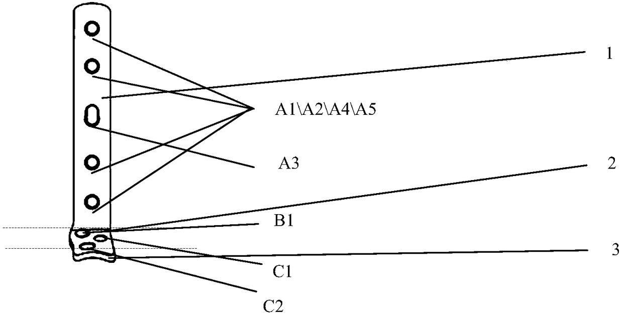
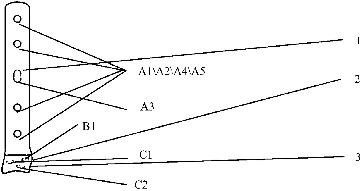
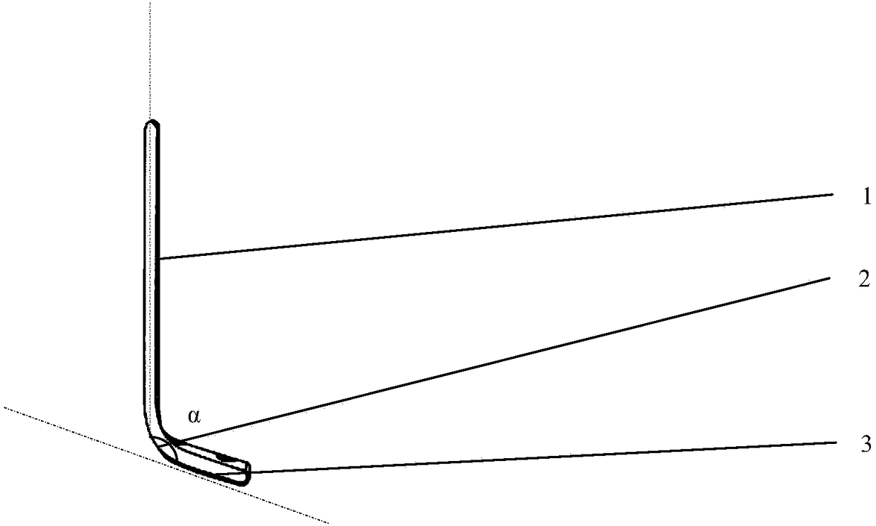
[0037] figure 1 , figure 2The structure of the present invention is shown. An anatomical, locking and pressurized internal fixation device for anterior tibiotalar joint fusion, comprising a tibial fixation part 1, a shape-shifting part 2 and a talar bone fixation part 3, the tibial fixation part 1, a shape-shifting part 2 and a talar bone fixation part 2 connected sequentially, the overall shape is "L", such as image 3 , 4 shown. For the convenience of expression, based on the front view, define the horizontal plane as x-plane, define the vertical plane perpendicular to the tibial fixation part panel and pass through the tibial fixation part longitudinal axis as y-plane, and define the plane parallel to and passing through the tibial fixation part as z-plane; Define the direction of the lateral malleolus a...


PUM


Abstract

The invention discloses a preposed tibiotalar joint fusion anatomy, locking and compression internal fixation device. The preposed tibiotalar joint fusion anatomy, locking and compression internal fixation device comprises a tibia fixing portion, a deformation portion and an ankle bone fixing portion. The tibia fixing portion, deformation portion and ankle bone fixing portion are connected sequentially. The tibia fixing portion is in arc connection with the ankle bone fixing portion by the deformation portion. The plate angle between the tibia fixing portion and the ankle bone fixing portion is 100-110 degrees. Screw holes vertical to the plate face are formed in a plate of the tibia fixing portion. The width direction of the deformation portion protrudes outwards and widens in an arc shape. Deformation portion locking screw holes are formed in the deformation portion. One side of the locating plane of the plate face of the connecting portion between the ankle bone fixing portion and the deformation portion protrudes outwards. Two locking screw holes are formed in the ankle bone fixing portion plate surface. One axial direction of the locking screw holes is not parallel to the normal direction of the ankle bone fixing portion plate surface. One axial direction near the front outer edge is parallel to the normal direction of the ankle bone fixing portion plate surface. Human engineering fitting design and optimized screw angle are adopted, stress on an internal fixing device is reduced, fixation stability is improved, and a certain function of an ankle joint is reserved.

Description

technical field [0001] The invention relates to an anatomical locking steel plate, in particular to an anatomical locking steel plate for tibiotalareal joint fusion lateral side. Orthopedic internal fixation device. Background technique [0002] In the advanced treatment of ankle degenerative diseases such as rheumatic / rheumatoid ankle arthritis, gouty ankle arthritis, post-traumatic ankle arthritis, and ankle osteoarthritis, ankle replacement—ankle replacement surgery is not Under the mature background, ankle joint fusion surgery is an effective treatment method under the current medical conditions, and it is also the surgical method that many patients have to choose. Clinical experience and research have confirmed that tibiotalar joint fusion can not only achieve the therapeutic effect of multiple ankle joint fusion, Moreover, it can retain a certain range of ankle joint mobility and improve the postoperative experience of patients. However, in the current internal fixati...

Claims


Application Information

Patent Timeline
Patent Type & Authority Applications(China)
IPC IPC(8): A61B17/80
CPCA61B17/8057A61B17/8061
Inventor 王本超金志辉
Owner 武汉大学人民医院
Why Eureka
Try Eureka