Special-shaped deep-cavity complex structure bracket hot extrusion forming mold and forming method

A technology of complex structure and forming molds, applied in the direction of metal extrusion molds, etc., can solve the problems of high scrap risk, high manufacturing cost, material consumption, etc., and achieve the effect of good surface quality, low cost and reasonable metal streamline.

Active Publication Date: 2020-06-19
BEIJING HANGXING MACHINERY MFG CO LTD
View PDF5 Cites 0 Cited by
  • Summary
  • Abstract
  • Description
  • Claims
  • Application Information

AI Technical Summary

Problems solved by technology

This method has serious disadvantages. For example, the material utilization rate is often lower than 30%, and the material consumption is serious; deformation occurs during the machining and heat treatment of castings, the risk of scrapping is high, and the manufacturing cost is high.

Method used


Image

  • Special-shaped deep-cavity complex structure bracket hot extrusion forming mold and forming method
  • Special-shaped deep-cavity complex structure bracket hot extrusion forming mold and forming method
  • Special-shaped deep-cavity complex structure bracket hot extrusion forming mold and forming method

Examples


Embodiment 1

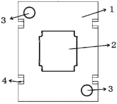
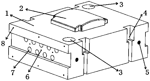
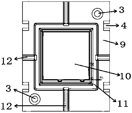
[0020] Such as Figure 1~6 As shown, a special-shaped deep cavity complex structure bracket forging hot extrusion die described in this embodiment includes an upper die 1, a lower die 9, a guide post 13, a guide sleeve 14, the lower surface of the upper die 1 and the lower The upper surface of the mold 9 is a horizontal plane, the lower surface of the upper mold 1 is provided with a punch 2, and the upper surface of the lower mold 9 is provided with a die 10 corresponding to the punch 2. The die 10 is a concave structure as a whole. 10 is provided with a flash groove 11, and a diversion groove 12 is respectively arranged around the flash groove 11. After the punch 2 and the die 10 are matched, there is a gap between the two, forming the shape of the bracket forging; adopting double guide pillars, Guide post holes 3 are respectively provided at the two diagonal corners of the upper die 1 and the lower die 9, the guide sleeve 14 is placed in the guide post hole 3, and the two ar...

Embodiment 2

[0023] Such as Figure 1~6 As shown, a special-shaped deep cavity complex structure bracket forging hot extrusion die described in this embodiment includes an upper die 1, a lower die 9, a guide post 13, a guide sleeve 14, the lower surface of the upper die 1 and the lower The upper surface of the mold 9 is a horizontal plane, the lower surface of the upper mold 1 is provided with a punch 2, and the upper surface of the lower mold 9 is provided with a die 10 corresponding to the punch 2. The die 10 is a concave structure as a whole. 10 is provided with a flash groove 11, and a diversion groove 12 is respectively arranged around the flash groove 11. After the punch 2 and the die 10 are matched, there is a gap between the two, forming the shape of the bracket forging; adopting double guide pillars, Guide post holes 3 are respectively provided at the two diagonal corners of the upper die 1 and the lower die 9, the guide sleeve 14 is placed in the guide post hole 3, and the two ar...


PUM

PropertyMeasurementUnit
radiusaaaaaaaaaa
radiusaaaaaaaaaa

Abstract

A hot extrusion forming mold and forming method for a special-shaped deep-cavity complex-structure support are disclosed. The mold includes an upper mold, a lower mold, guide columns and guide sleeves. The lower surface of the upper mold and the upper surface of the lower mold are horizontal surfaces. The lower surface of the upper mold is provided with a punch, and the upper surface of the lowermold is provided with a matrix corresponding to the punch, with the matrix having an inward concave structure and the periphery of the matrix being provided with a flash cavity. The four sides of theflash cavity are provided with guide slots. A gap is left between the punch and the matrix after assembling to form the shape of a support forge piece. Two angle positions of a diagonal line of the upper mold and the lower mold are provided with guide column holes correspondingly, with one guide sleeve being disposed in each guide column hole. The guide sleeves and the corresponding guide column holes are fastened in a press fit manner. The upper mold and the lower mold are positioned through inserting the guide columns into the corresponding guide sleeves of the upper mold and the lower moldrespectively. Through the design of the punch, the matrix, the flash cavity and the guide slots, blank material flowing is controlled so as to control the dimension precision of the support forge piece, and an excessive blank material can be discharged.

Description

technical field [0001] The invention relates to the technical field of mechanical processing equipment, in particular to a special-shaped deep cavity complex structure bracket hot extrusion forming die. Background technique [0002] The general trend of national defense security requires that the response speed of weapons and equipment replacement is getting faster and faster, and the technical and tactical indicators are getting higher and higher. Weapons and equipment gradually show the characteristics of lightweight, complex and integrated structures, and the requirements for the ratio of components to weight and strength continue to increase. , the contradiction between structural lightweight and high-strength requirements is becoming more and more prominent. In order to meet the above requirements, a large number of light alloy special-shaped complex thin-walled structures are used in aerospace weapon components. Among them, the cross-section of a certain type of aeros...

Claims


Application Information

Patent Timeline
Patent Type & Authority Patents(China)
IPC IPC(8): B21C25/02B21C23/00
CPCB21C23/001B21C25/02B21C25/025
Inventor 王胜龙郭晓琳王志敏吴凯东栋周小京尤逢海
Owner BEIJING HANGXING MACHINERY MFG CO LTD
Why Eureka
Try Eureka