Automatic warm upsetting machine

A warm upsetting machine, automatic technology, applied in forging presses, forging presses, forging/pressing/hammering machines, etc., can solve problems such as cost increase, uneven cutting section, and shortened service life of die frame and die core. Ensure production quality, ensure flatness and outer circle, and reduce mutual wear effects

Pending Publication Date: 2018-12-07
谢兵
View PDF0 Cites 4 Cited by
  • Summary
  • Abstract
  • Description
  • Claims
  • Application Information

AI Technical Summary

Problems solved by technology

[0002] Existing warm heading machines generally use a unidirectional cutter to cut the raw material rod body. During the cutting process, the raw material rod body will be deformed due to unidirectional force, making the cutting section of the raw material to be processed uneven. The outer circle is elliptical, which will seriously affect the quality of the processed workpiece in the subsequent processing. The products produced have many burrs, the end faces of the products are defective, and there are many waste products.
In addition, due to the improvement of stamping technology and equipment in the existing warm upsetting machine, the mold frame and mold core in the forming mold of the warm upsetting machine are generally opened and closed with cylindrical or conical bonding surfaces, but when the warm upsetting machine It is a horizontal warm heading machine. Due to the influence of gravity, the lower edge of the mold core and the mold frame are forced to fit together. During the process of opening and closing the mold for many times, because there is only one edge that fits under the force, this position wears out. Seriously affect production, resulting in a significant reduction in the service life of the entire mold frame and mold core, increased cost and difficult maintenance

Method used


Image

  • Automatic warm upsetting machine
  • Automatic warm upsetting machine
  • Automatic warm upsetting machine

Examples


Embodiment Construction

[0023] The following will clearly and completely describe the technical solutions in the embodiments of the present invention with reference to the accompanying drawings in the embodiments of the present invention. Obviously, the described embodiments are only some, not all, embodiments of the present invention. Based on the embodiments of the present invention, all other embodiments obtained by persons of ordinary skill in the art without making creative efforts belong to the protection scope of the present invention.

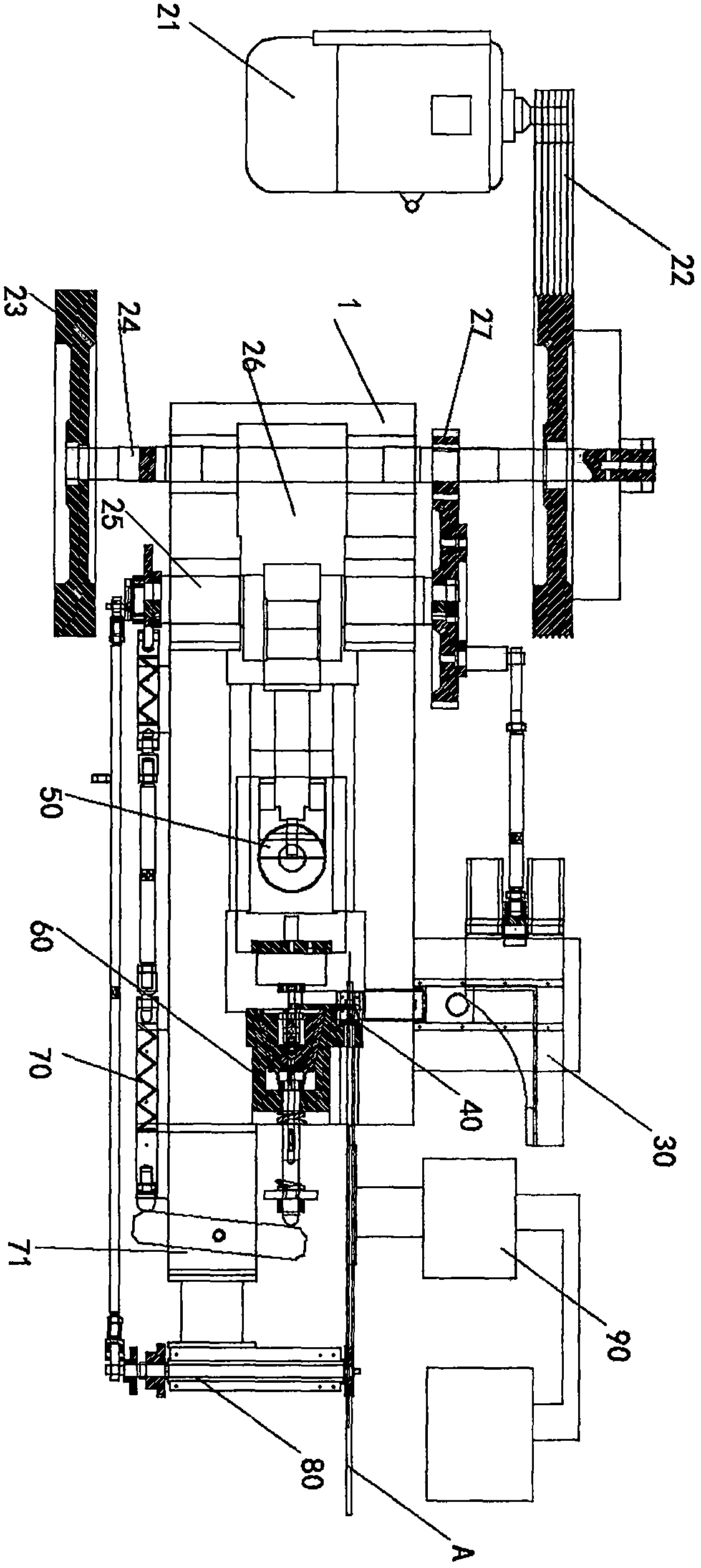
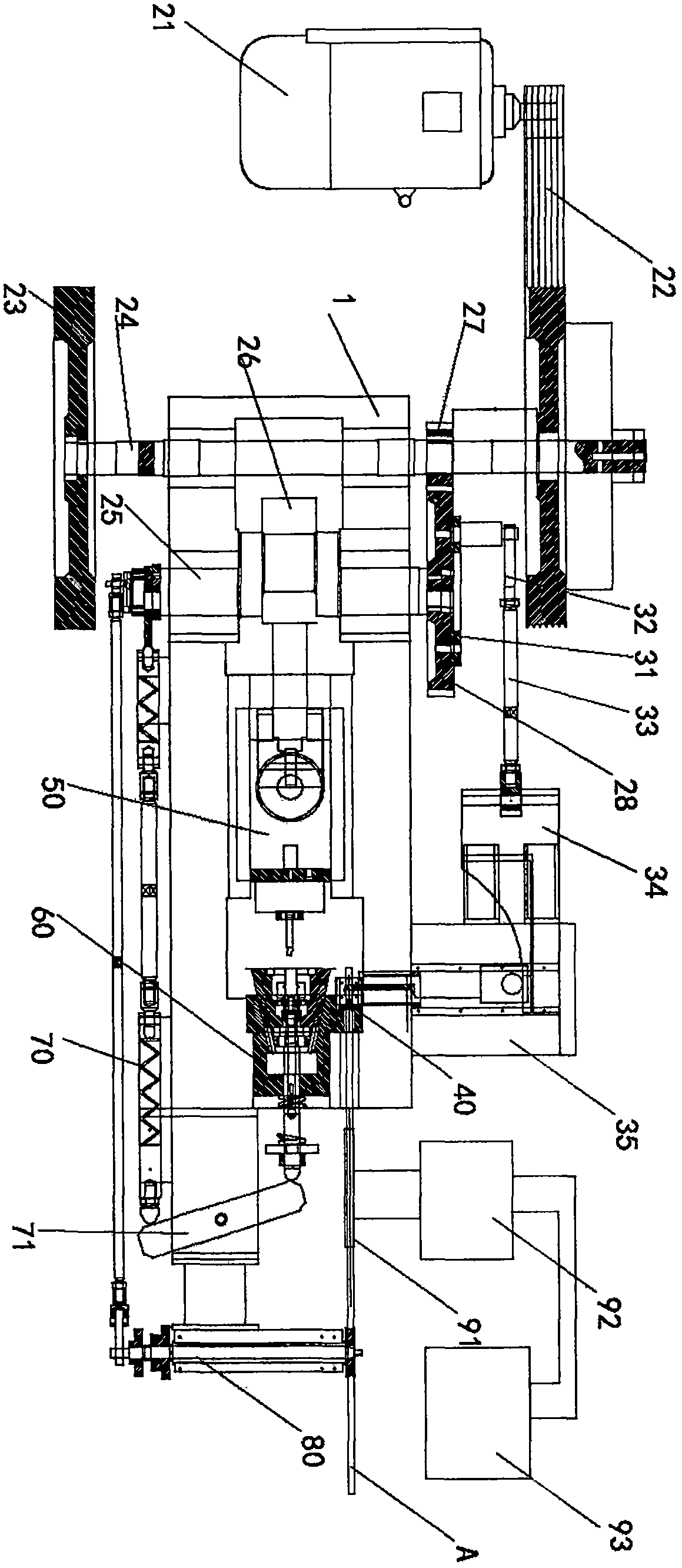
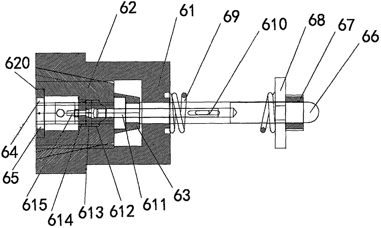
[0024] see Figure 1-9, an automatic warm heading machine according to an embodiment of the present invention, comprising a body 1 and an electric transmission device arranged on the body, an upsetting device, a parting and ejecting device, a forming die device 60, a feeding device 80, and a cutting device 40 , the heating device 90 and the feeding device 30, wherein the electric transmission device includes a motor 21, a flywheel 22 connected with the motor, ...


PUM


Abstract

The invention discloses an automatic warm upsetting machine. A cutting device of the automatic warm upsetting machine comprises a cutting seat, a cutting mold and two cutting knife sets symmetricallyarranged at the two ends of a raw material to cut off the raw material. The cutting mold is in clamped connection to the center of the cutting seat. A sleeving hole is formed in the center of the cutting mold to be in sleeved connection with the raw material in a cooperation manner. A forming mold comprises a mold frame, mold cores capable of achieving mold compounding and opening along the innerend face of the mold frame, forming mold bodies arranged in gap grooves at the inner ends of the mold core and a mold compounding and opening assembly driving the mold cores to achieve mold compounding and opening. Square gap mold compounding grooves cooperating with the mold cores for mold compounding are arranged at the inner end of the mold frame. According to the automatic warm upsetting machine, the mold cores and the mold frame are attached to the end face of the inner cavity, square design is adopted, wear-resisting inserts are used in a matched manner, and mutual wear of the lower endfaces of the mold cores and the mold frame at the mold compounding and opening moment is reduced to the largest extent; and the bidirectional hydraulic cutting knife sets are adopted for cutting the raw material, cutting is achieved bidirectionally at the same time, bidirectional stress can guaranteed that a cut surface is level and an outer circle does not deform, and the product production quality is ensured.

Description

technical field [0001] The invention relates to the technical field of forging equipment, in particular to an automatic warm heading machine. Background technique [0002] Existing warm heading machines generally use a unidirectional cutter to cut the raw material rod body. During the cutting process, the raw material rod body will be deformed due to unidirectional force, making the cutting section of the raw material to be processed uneven. The outer circle is elliptical, which will seriously affect the quality of the processed workpiece in subsequent processing. The products produced have many burrs, defective end faces and many waste products. In addition, due to the improvement of stamping technology and equipment in the existing warm upsetting machine, the mold frame and mold core in the forming mold of the warm upsetting machine are generally opened and closed with cylindrical or conical bonding surfaces, but when the warm upsetting machine It is a horizontal warm hea...

Claims


Application Information

Patent Timeline
IPC IPC(8): B21J9/08B21K27/06B21J13/02
CPCB21J9/08B21J13/02B21K27/06
Inventor 谢兵
Owner 谢兵
Why Eureka
Try Eureka