Power system for hybrid vehicles
A hybrid vehicle and power system technology, applied in the field of hybrid vehicles, can solve problems such as poor adaptability and single structure, and achieve the effect of increasing torque
- Summary
- Abstract
- Description
- Claims
- Application Information
AI Technical Summary
Problems solved by technology
Method used
Image

Examples
Embodiment 1
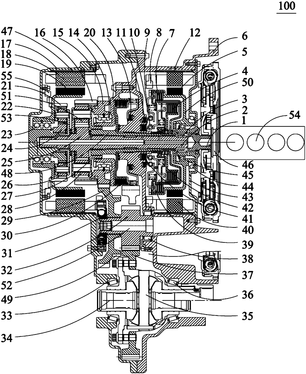
[0032] figure 1 is a schematic structural diagram of a power system 100 according to an embodiment of the present invention. The power system 100 of the present invention is not only applicable to vehicles with a two-wheel drive transmission mechanism, but also applicable to vehicles with a four-wheel drive transmission structure. Such as figure 1 As shown, the power system 100 mainly includes an engine 54 , a first motor 101 , a second motor 102 , a first planetary gear mechanism 104 , a first input shaft 2 , a first clutch 7 , and a brake 30 . The first motor 101 includes a first stator 40 and a first rotor 5 , and the second motor 102 includes a second stator 18 and a second rotor 19 . The engine 54 and the first motor 101 are connected in transmission, and the first clutch 7 is arranged between the first motor 101 and the first input shaft 2, so as to cut off or combine the first motor 101 and the first input shaft 2 through the first clutch 7 power transmission. The f...
Embodiment 2
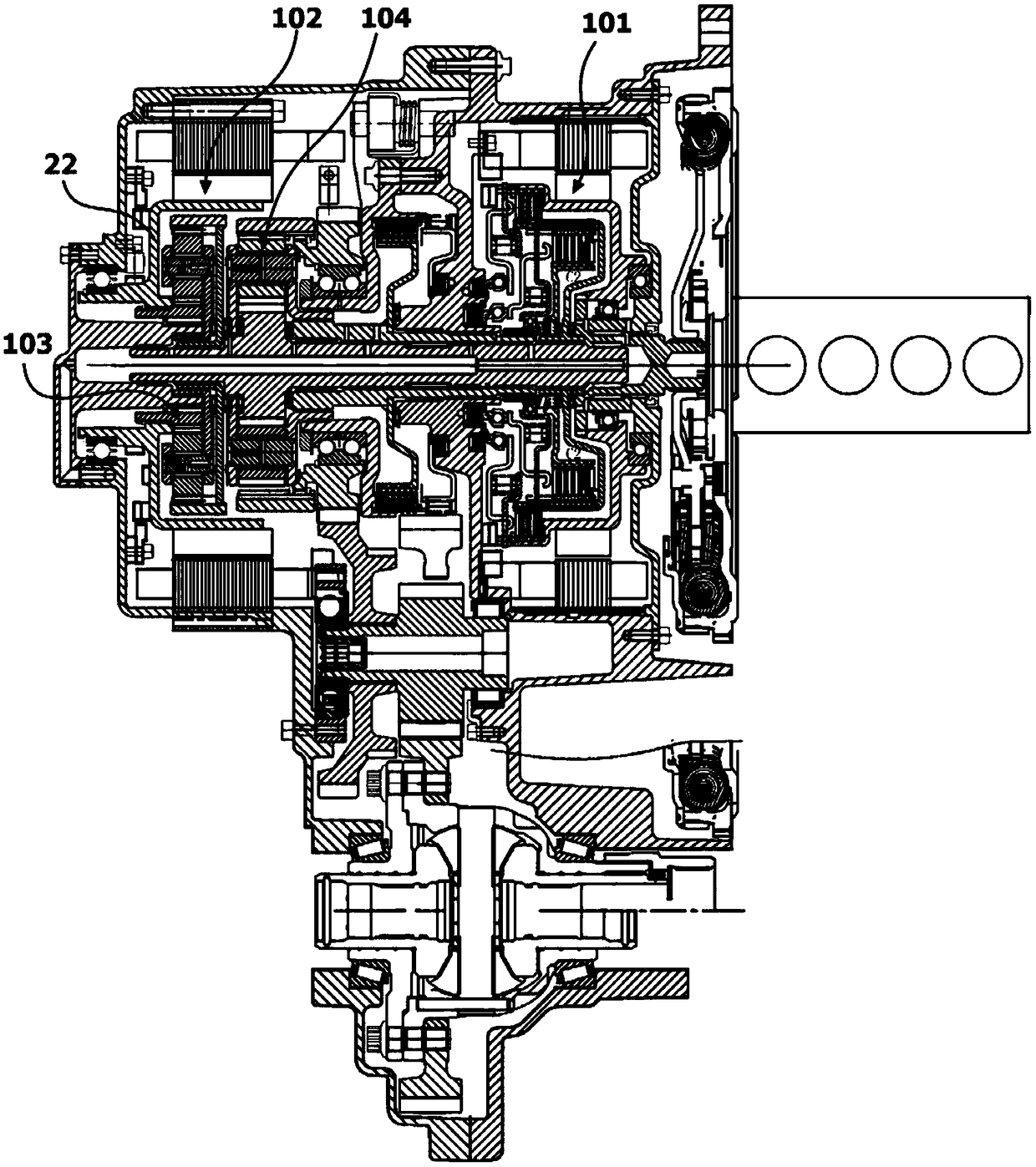
[0073] figure 2 is a schematic structural diagram of a power system 100 according to another embodiment of the present invention. If a larger reduction ratio is required, the second planetary gear mechanism 103 can adopt different coupling methods. In this embodiment, the second motor and the first input shaft are arranged coaxially. refer to figure 2 , the second sun gear 24 is fixed on the second rotor 19 of the second motor 102 and rotates together with the second rotor 19, specifically, the second sun gear 24 is connected to the second rotor 19 of the second motor 102 through the rotor support plate 22 For transmission connection, the second planet carrier 53 is installed on the rear housing 17 and fixed relative to the rear housing 17 , and the second ring gear 21 is in transmission connection with the first input shaft 2 . The second motor 102 transmits power to the first input shaft 2 through the second ring gear 21 . With the above structure, a large reduction ra...
Embodiment 3
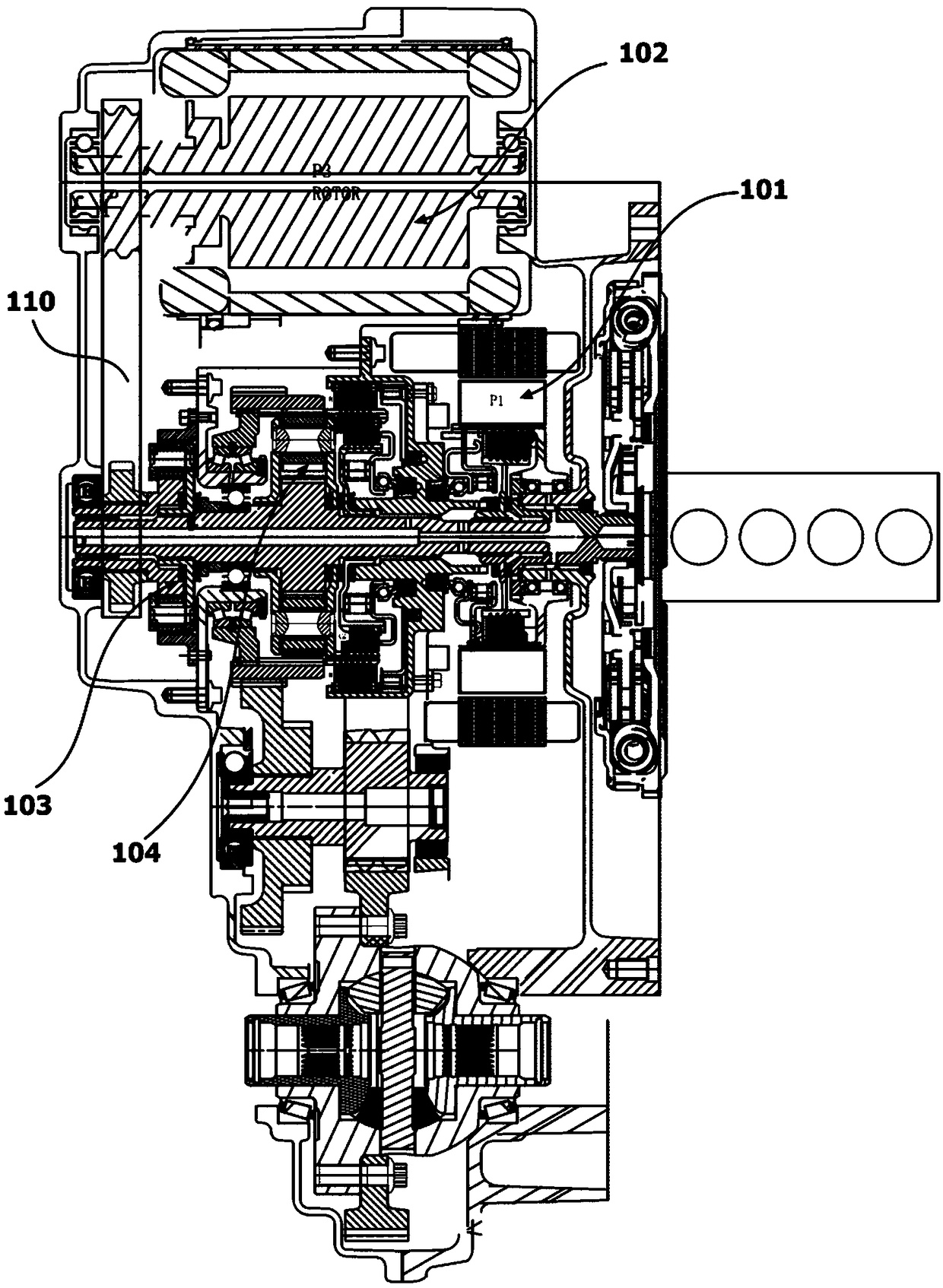
[0076] image 3 is a schematic structural diagram of a power system 100 according to yet another embodiment of the present invention. Such as image 3 As shown, in this embodiment, the first motor (P1) is arranged in the same manner as the above embodiment, and the second motor (P3) is arranged off-axis from the first input shaft. The second sun gear 24 is drivingly connected with the second rotor 19 of the second motor 102 through the transmission chain 110. The second ring gear 21 is installed on the rear housing 17 and is fixed relative to the rear housing 17. The second motor 102 is connected by the second planetary The frame 53 transmits power to the first input shaft 2 . In this embodiment, except for the connection between the second motor 102 and the first input shaft 2 , other connection structures and operation modes are not much different from those in Embodiment 1, so no more details are given here.
PUM
 Abstract
Description
Claims
Application Information
 - Generate Ideas
- Intellectual Property
- Life Sciences
- Materials
- Tech Scout
- Unparalleled Data Quality
- Higher Quality Content
- 60% Fewer Hallucinations
Browse by: Latest US Patents, China's latest patents, Technical Efficacy Thesaurus, Application Domain, Technology Topic, Popular Technical Reports.
© 2025 PatSnap. All rights reserved.Legal|Privacy policy|Modern Slavery Act Transparency Statement|Sitemap|About US| Contact US: help@patsnap.com