Eureka AIR delivers breakthrough ideas for toughest innovation challenges, trusted by R&D personnel around the world.

High-speed rubber track and high-speed rubber track pattern side rubber

A technology of rubber crawler and side rubber, which is applied in the field of high-speed rubber crawler and high-speed rubber crawler pattern side rubber, can solve the problems of large effect, low efficiency, slow speed, etc., achieve fast and stable walking, and enhance tensile strength. , the effect of reducing damage

Pending Publication Date: 2018-12-07
YACHOO TECH CO LTD
View PDF12 Cites 4 Cited by
  • Summary
  • Abstract
  • Description
  • Claims
  • Application Information

AI Technical Summary

Problems solved by technology

[0002] In some special environments and specific occasions, such as national defense, anti-riot, rescue, investigation and other special affairs, some special personnel are required to investigate the scene, investigate, remove, and eliminate hidden dangers and dangers of uncertain factors at close range, so that It poses a great security risk to special personnel
In recent years, with the continuous development of drone remote control technology, drones can do some investigation work, but some special working conditions and areas still require some ground investigation equipment to lead or participate in investigation, execution, release and other matters. Usually, the walking or moving modes of these devices are wheeled and crawler-type. The wheel-type has the advantages of fast speed and strong versatility of tires, while the crawler-type has the advantages of strong passability, strong obstacle-crossing ability, small grounding specific pressure, It has the advantages of large traction, but its speed is slower than that of the wheel type, and it is difficult to realize the steering through the driving structure
[0003] Existing tracked vehicles generally travel at speeds within 30Km / h. Such a slow speed also affects and reduces the proper performance of special vehicles. When dealing with certain affairs, there will be powerlessness and low efficiency. The effect is big fight
Moreover, the existing tracked vehicles are commonly used with rigid structure chassis. However, the rigid structure chassis has problems such as instability when walking, large vibration, etc., which will bring many negative effects on the relevant high-precision components and imaging equipment on the body.

Method used


Image

  • High-speed rubber track and high-speed rubber track pattern side rubber
  • High-speed rubber track and high-speed rubber track pattern side rubber
  • High-speed rubber track and high-speed rubber track pattern side rubber

Examples


preparation example Construction

[0034] The preparation method of high-speed rubber track of the present invention is as follows:

[0035] 1. Preparation of wheel side rubber 2

[0036] The material formula and the manufacturing method of wheel side rubber 2 can be identical with driving tooth 5.

[0037] 2. Preparation of guide teeth 4

[0038] 2.1. Plasticizing the main rubber material of the guide gear 4: put NR RSS3, SBR 1502, and BR900 into the internal mixer for plasticizing, and discharge the glue at 165°C in the actual measurement. parked for more than 8 hours;

[0039] 2.2. Carry out the first stage of mixing of the guide gear 4: put the rubber main material masticated in 2.1 into the internal mixer, and masticate again, the masticating time is 40-60 seconds, and the speed is 40-50 rpm After the mastication is completed, add zinc oxide, stearic acid, dispersant FS210, anti-aging agent RD, anti-aging agent 4010, C5 resin and carbon fiber, and at the same time, add carbon black N220 and white carbon...

Embodiment 1

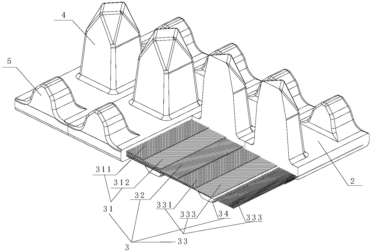
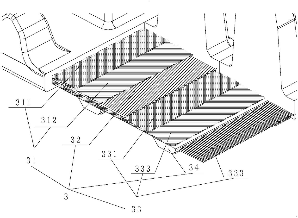
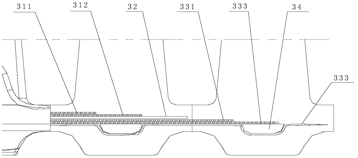
[0059] In this embodiment, the first composite support layer 31 is sequentially the first inclined support layer 311 and the second inclined support layer 312 from the inside to the outside, and the laying direction of the first inclined support layer 311 is in line with the track The included angle in the width direction is 45 degrees, and the second inclined support layer 312 is laid at an angle of 90 degrees relative to the first inclined support layer 311; the second composite support layer 33 is in order from inside to outside: The third inclined supporting layer 331, the fourth inclined supporting layer 332 and the flat supporting layer 333, the laying direction of the third inclined supporting layer 331 is the same as that of the first inclined supporting layer 311, the fourth inclined supporting layer 331 The laying direction of the supporting layer 332 is the same as that of the second inclined supporting layer 312, and the laying of the flat supporting layer 333 is pa...

Embodiment 2

[0068] The difference from Embodiment 1 is that the angle between the laying direction of the first inclined support layer 311 and the track width direction is 30 degrees, and the second inclined support layer 312 is opposite to the first inclined support layer. 311 is laid at an angle of 120 degrees; the supporting material selected is polyester fiber cloth.

[0069] The small vertical grooves 111 are inclined at an angle of 8 degrees relative to the circumferential direction of the track.

[0070] The length of the support core 34 is 20mm shorter than the width of the rubber track.

[0071] The height of the guide teeth 4 is 100mm.

[0072] The material formula of the guide tooth 4 is calculated by weight: 85 parts of NR RSS3, 15 parts of SBR 1502, 15 parts of BR9000, 78 parts of carbon black N220, 13 parts of white carbon black, 4.5 parts of zinc oxide, 2 parts of stearic acid, 3 parts of dispersant FS210, 2.5 parts of anti-aging agent RD, 2 parts of anti-aging agent 4010...


PUM

PropertyMeasurementUnit
Shore hardnessaaaaaaaaaa
heightaaaaaaaaaa
hardnessaaaaaaaaaa

Abstract

The high-speed rubber track of the invention comprises a pattern side rubber and a wheel side rubber, and a skeleton arranged between the pattern side rubber and the wheel side rubber; The surface ofthe wheel side rubber is provided with a pattern, and the surface of the wheel side rubber is provided with a guide tooth and a driving tooth along the circumference of the track according to the pitch of the driving wheel; Characterized in that the skeleton comprises a first composite support layer, an intermediate strength layer and a second composite support layer arranged in sequence from theinside to the outside; The first composite support layer and the second composite support layer are each composed of 1-3 layers of supporting materials laid in a cross-shaped manner; The intermediatestrength layer is formed by wrapping aramid fibers along the circumferential direction of the track. The invention has the advantages of strong adaptability and small vibration when the vehicle is running, and can play the role of protecting the related high-precision components and image equipment on the vehicle body. Rubber track has tensile, anti-crimping skeleton design in the transverse direction, enhance the tensile strength in the circumferential and width of of the track, so that tracked vehicles can move quickly and stably.

Description

technical field [0001] The invention relates to the technical field of rubber crawler production, in particular to a high-speed rubber crawler and a pattern side rubber of the high-speed rubber crawler. Background technique [0002] In some special environments and specific occasions, such as national defense, anti-riot, rescue, investigation and other special affairs, some special personnel are required to investigate the scene, investigate, remove, and eliminate hidden dangers and dangers of uncertain factors at close range, so that It has brought great security risks to special personnel. In recent years, with the continuous development of drone remote control technology, drones can do some investigation work, but some special working conditions and areas still require some ground investigation equipment to lead or participate in investigation, execution, release and other matters. Usually, the walking or moving modes of these devices are wheeled and crawler-type. The wh...

Claims


Application Information

Patent Timeline
Patent Type & Authority Applications(China)
IPC IPC(8): B62D55/24B62D55/26C08L7/00C08L9/06C08L9/00C08L57/02C08K13/02C08K3/04C08K3/36C08K3/22C08K5/09C08K7/06C08K5/18
CPCB62D55/24B62D55/26C08L7/00C08L2205/035C08K2003/2296C08L9/06C08L9/00C08L57/02C08K13/02C08K3/04C08K3/36C08K3/22C08K5/09C08K7/06C08K5/18
Inventor 徐贤坤江灵志刘华阳
Owner YACHOO TECH CO LTD
Why Eureka
Eureka Blog
Learn More