Bearing receiving device

A technology of a receiving device and a discharging device, which is applied in the field of bearing transportation, can solve the problems of increasing the labor intensity of the staff and not being better, and achieve the effects of simple structure, improved production efficiency, and reduced labor intensity

Active Publication Date: 2018-12-07
BENGBU FEIYU BEARING
View PDF8 Cites 4 Cited by
  • Summary
  • Abstract
  • Description
  • Claims
  • Application Information

AI Technical Summary

Problems solved by technology

[0003] At present, a high degree of automation has been achieved in the production process of bearings, which has greatly improved production efficiency. However, there are some problems to be solved in actual production. Among them, at the end of the production line, there are generally no better The bearing receiving device is used to complete the automatic receiving, which requires manual receiving, which increases the labor intensity of the staff

Method used


Image

  • Bearing receiving device
  • Bearing receiving device
  • Bearing receiving device

Examples


Embodiment 1

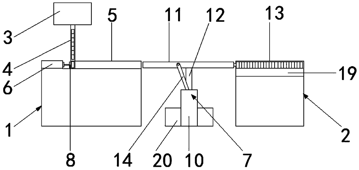
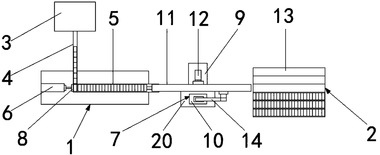
[0020] Such as figure 1 As shown, a bearing receiving device includes a pushing mechanism 1 and a stacking mechanism 2. The pushing mechanism 1 is adjacent to a discharge device 3, and the discharge device 3 passes through a discharge channel arranged obliquely downward. 4 is connected to the pusher mechanism 1, and the pusher mechanism 11 is provided with a horizontal first stacking chute 5 at the junction of the discharge channel 4, and one end of the first stacker 5 is adjacent to the discharge channel 4. The electro-hydraulic push rod 6 is provided with a transmission mechanism 7 adjacent to the other end, and the front end of the electro-hydraulic push rod 6 is provided with a product push plate 8, and the transmission mechanism 7 includes a base 9, a rocker drive mechanism 10, an electric telescopic rod 11. The base 9 is fixedly connected with a support rod 12, and the support rod 12 articulates the electric telescopic rod 11, and the other side of the electric telescopi...

Embodiment 2

[0024] Such as figure 1 As shown, a bearing receiving device includes a pushing mechanism 1 and a stacking mechanism 2. It is characterized in that: the pushing mechanism 1 is adjacent to a discharge device 3, and the discharge device 3 is arranged obliquely downward The discharge passage 4 is connected with the push mechanism 1, and the push mechanism 11 is provided with a horizontal first stacking chute 5 at the junction of the discharge passage 4, and the first stack trough 5 is adjacent to the discharge passage 4 One end is provided with an electro-hydraulic push rod 6, and the other end is adjacent to a transmission mechanism 7, and the front end of the electro-hydraulic push rod 6 is provided with a product push plate 8, and the transmission mechanism 7 includes a base 9, a rocker drive mechanism 10 , electric telescopic rod 11, described base 9 is fixedly connected with support rod 12, and described support rod 12 articulates described electric telescopic rod 11, and th...


PUM


Abstract

The invention relates to the field of bearing conveying, in particular to a bearing receiving device. The bearing receiving device comprises a pushing mechanism and a stacking mechanism, wherein a transverse first stacking groove is formed in the joint of the pushing mechanism and a discharging channel, and an electro-hydraulic push rod is arranged at one end, close to the discharging channel, ofthe first stacking groove; and a transmission mechanism comprises a base, a rocker driving mechanism and an electric telescopic rod, wherein the base is fixedly connected with a supporting rod, the supporting rod is movably hinged to the electric telescopic rod, the other side of the electric telescopic rod connected with the supporting rod is movably hinged with the rocker driving mechanism, oneend, far away from the pushing mechanism, of a conveying mechanism is provided with the stacking mechanism. The bearing receiving device is simple in structure, safe and reliable; under the driving ofthe rocker driving mechanism, the electric telescopic rod reciprocates between the first stacking groove and a second stacking groove, and meanwhile, the electric telescopic rod movably sleeves witha bearing through stretching and retracting, so that high automation material collecting is achieved, and manual investment is greatly reduced.

Description

Technical field: [0001] The invention relates to the field of bearing conveying, in particular to a bearing receiving device. Background technique: [0002] Bearing is an important basic component of various mechanical equipment, its precision, performance, life and reliability play a decisive role in the accuracy, performance, life and reliability of the main engine. Among mechanical products, bearings are high-precision products, which not only require the comprehensive support of mathematics, physics and many other disciplines, but also require material science, heat treatment technology, precision machining and measurement technology, numerical control technology and effective numerical methods and powerful computers. Technology and many other disciplines serve it, so the bearing is a product that represents the country's scientific and technological strength. [0003] At present, a high degree of automation has been achieved in the production process of bearings, which...

Claims


Application Information

Patent Timeline
Patent Type & Authority Applications(China)
IPC IPC(8): B65G47/82B65G47/74
CPCB65G47/74B65G47/82
Inventor 戴宇凯周成武李明海徐瑞祥程明刚
Owner BENGBU FEIYU BEARING
Why Eureka
Try Eureka