Fabricated self-resetting basic system

A prefabricated and basic technology, applied in the direction of infrastructure engineering, wine cellars, building components, etc., can solve the problems of only usable foundation, missing connections, waste, etc., and achieve improved space utilization, simple construction technology, and easy stacking and storage Effect

Pending Publication Date: 2018-12-07
上海同派建筑科技有限公司
View PDF4 Cites 2 Cited by
  • Summary
  • Abstract
  • Description
  • Claims
  • Application Information

AI Technical Summary

Problems solved by technology

However, some new problems have been exposed in practice: there are many types of prefabricated foundations with different functions, but they are all prefabricated by factories after design, the foundations can only be used for predetermined projects, and the molds for producing foundations can only It is dedicated to special projects, and the basics are more versatile, and the molds cannot be reused in different projects, causing another waste
[0004] At present, some improvements have been made to the prefabricated foundation. For example, the Chinese patent with the publication number CN106836269A on June 13, 2017 discloses a prefabricated fast-installation basic structure, which achieves a high degree of assembly, and It can be disassembled and reused, but the structural integrity is poor because the connection between the first base unit and the second base unit is missing in the middle
In addition, the prefabricated foundation is not conducive to synergy due to the "looseness" of each component. Therefore, it is necessary to introduce a self-recovering component with high pre-tightening force, such as a shape memory alloy screw.

Method used


Image

  • Fabricated self-resetting basic system
  • Fabricated self-resetting basic system
  • Fabricated self-resetting basic system

Examples


Embodiment Construction

[0035] The present invention will be further described below in conjunction with the accompanying drawings and specific implementation examples.

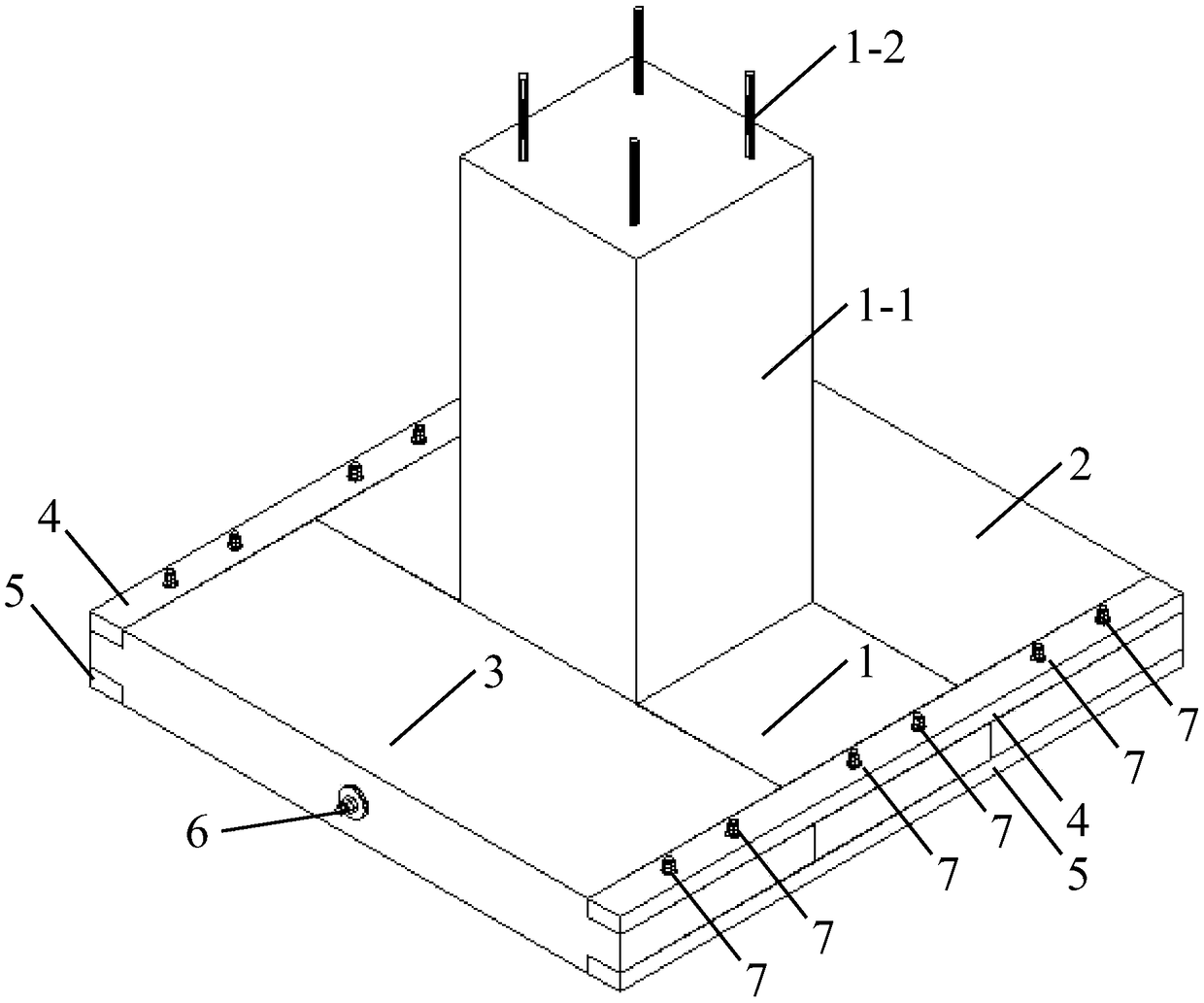
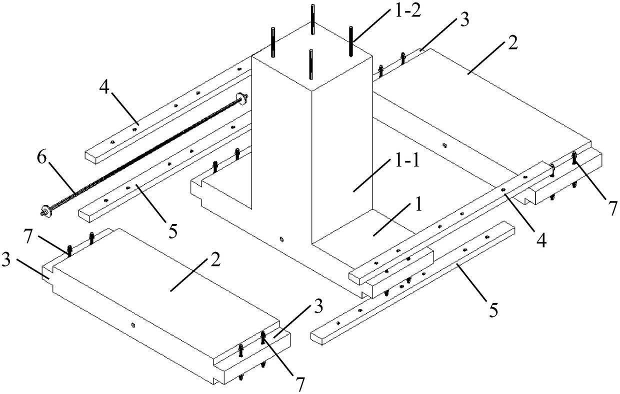
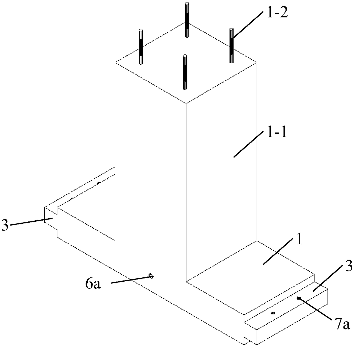
[0036] combine Figure 1 to Figure 4 As shown, an assembled self-recovering foundation system includes a main foundation unit 1 and two sub-basic units 2 spliced ​​on the sides of the main foundation unit; Symmetrical stepped sinker 3, the stepped sinker 3 has installation through holes 7a and 7b through up and down; the upper beam 4 is fitted in the stepped sinker 3 on the upper side, and the stepped sinker 3 on the lower side The lower crossbeam 5 is fitted inside; the corresponding upper crossbeam 4 and lower crossbeam 5 on each side are connected by steel bolts 7; the middle openings 6a and 6b of the main foundation unit 1 and the auxiliary foundation unit 2 are pre-tensioned The shape-memory alloy screw rod 6 of the pull connects the main and auxiliary foundations together. The main basic unit 1 and the auxiliary basic unit 2...


PUM

PropertyMeasurementUnit
Diameteraaaaaaaaaa
Diameteraaaaaaaaaa

Abstract

The invention discloses a fabricated self-resetting basic system and belongs to the field of buildings. The fabricated self-resetting basic system comprises a main basic unit and a plurality of auxiliary basic units spliced on the side of the main basic unit. Symmetric stepped countersinks are formed in the upper sides and the lower sides of the two ends of the main basic unit and the auxiliary basic units correspondingly, and vertically through mounting through holes are formed in the bottoms of the countersinks. Upper cross beams are placed in the countersinks in the upper side in a matchedmanner, and lower cross beams are placed in the countersinks in the lower side in a matched manner. The corresponding upper cross beam and lower cross beam on each side are connected through a bolt. Holes are formed in the middle of the main basic unit and the middles of the auxiliary basic units, and the main basic unit and the auxiliary basic units are connected together through pretension shapememory alloy screw rods. The fabricated self-resetting basic system has the beneficial effects of being simple in fabrication process, convenient to transport, convenient to assemble, fast to construct, capable of being freely fabricated, good in self-resetting performance and the like. According to different stress requirements, different basic units and cross beams can be combined, overall scheme changing is not needed, construction efficiency is improved, and cost is reduced.

Description

technical field [0001] The invention belongs to the technical field of civil engineering, in particular to an assembled self-restoring foundation suitable for light steel structure houses, communication base stations, power transmission line towers and other buildings. Background technique [0002] The traditional independent foundation under the column generally adopts the form of reinforced concrete pouring on site, so it is necessary to pour concrete on the construction site, and it is necessary to wait for the concrete to form an early strength before continuing the construction of the superstructure. This is not suitable for projects with a short construction period such as light steel structure houses, communication base stations, and transmission line towers, and even the foundation construction time will account for more than half of the total construction period. [0003] The prefabricated foundation is being widely used in the above-mentioned projects because of it...

Claims


Application Information

Patent Timeline
IPC IPC(8): E02D27/42E02D27/01E04B1/00
CPCE02D27/016E02D27/42E04B1/0007
Inventor 邵红亮喻月梁政姬
Owner 上海同派建筑科技有限公司
Why Eureka
Try Eureka