Ultraviolet light disinfection toilet

A technology of ultraviolet rays and toilets, applied in flushing equipment with water tanks, flushing toilets, irradiation, etc., can solve problems such as difficult cleaning, affecting normal use of toilets, and inability to save water resources, so as to reduce waste of water resources and disinfect Good effect and improved convenience

Inactive Publication Date: 2018-12-07
杭州国瑞数码科技有限公司
View PDF0 Cites 4 Cited by
  • Summary
  • Abstract
  • Description
  • Claims
  • Application Information

AI Technical Summary

Problems solved by technology

[0003] In the existing market, ultraviolet light is mostly used on the toilet, and the ultraviolet C light is used to irradiate the toilet cover and other positions to sterilize the toilet cover, which has the effect of environmental protection and hygiene; Only clean tap water can be used for flushing, because the tap water has been disinfected and sterilized in the early stage, so the bacteria content in the toilet tank and other places is small, and there is no need to sterilize, but the flushing volume of the toilet is large. A large amount of water resources will be wasted in the process, and the effect of saving water resources and reducing water consumption cannot be realized
[0004] At present, domestic sewage has been used to flush the toilet in the market, but the current domestic sewage has a lot of dirt and bacteria in the process of use, so when it enters the toilet tank, it will cause bacteria in the toilet tank. increase, a large number of bacteria will enter the toilet bowl during the flushing process, and further volatilize into the air, resulting in a large number of bacteria in the entire bathroom environment; and when using domestic wastewater to flush the toilet When the toilet is used, a small amount of sewage will remain in the toilet bowl, which will cause the inner wall of the toilet bowl to become dirty, which is difficult to clean and affect the normal use of the toilet.

Method used


Image

  • Ultraviolet light disinfection toilet
  • Ultraviolet light disinfection toilet
  • Ultraviolet light disinfection toilet

Examples


Embodiment Construction

[0034] In order to enable those skilled in the art to better understand the solutions of the present invention, the technical solutions in the embodiments of the present invention will be clearly and completely described below in conjunction with the drawings in the embodiments of the present invention.

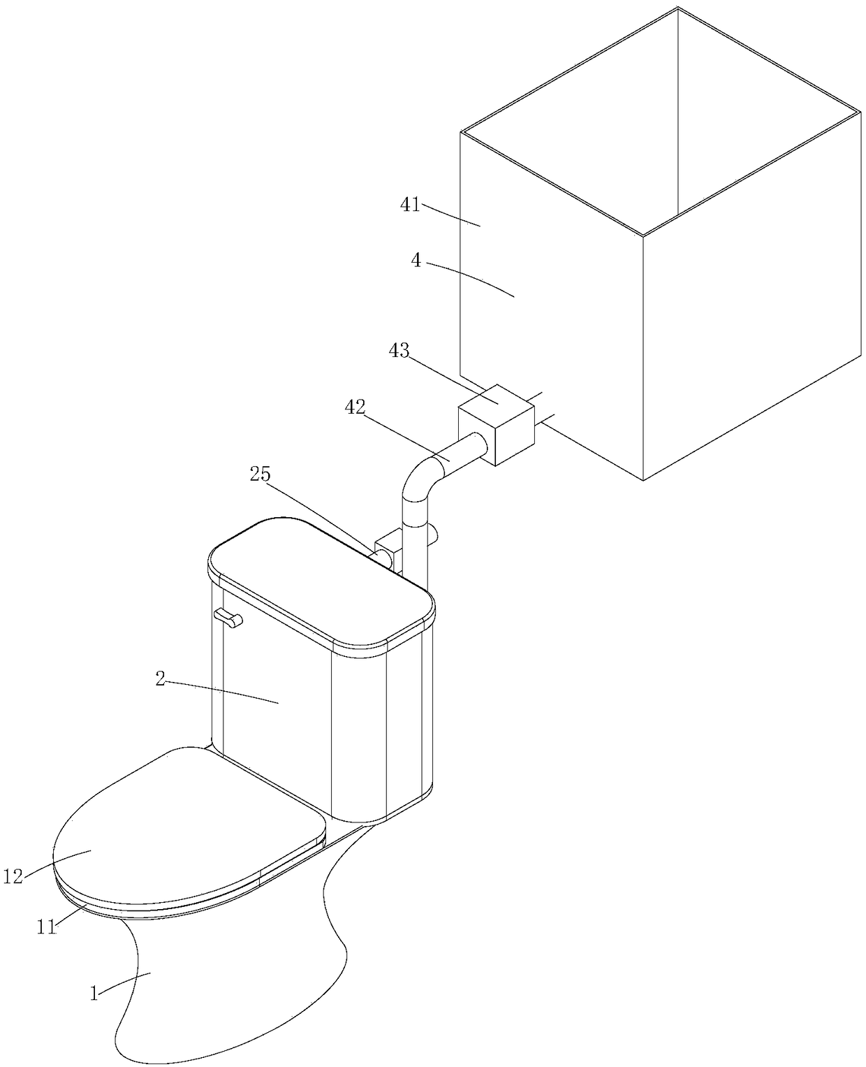
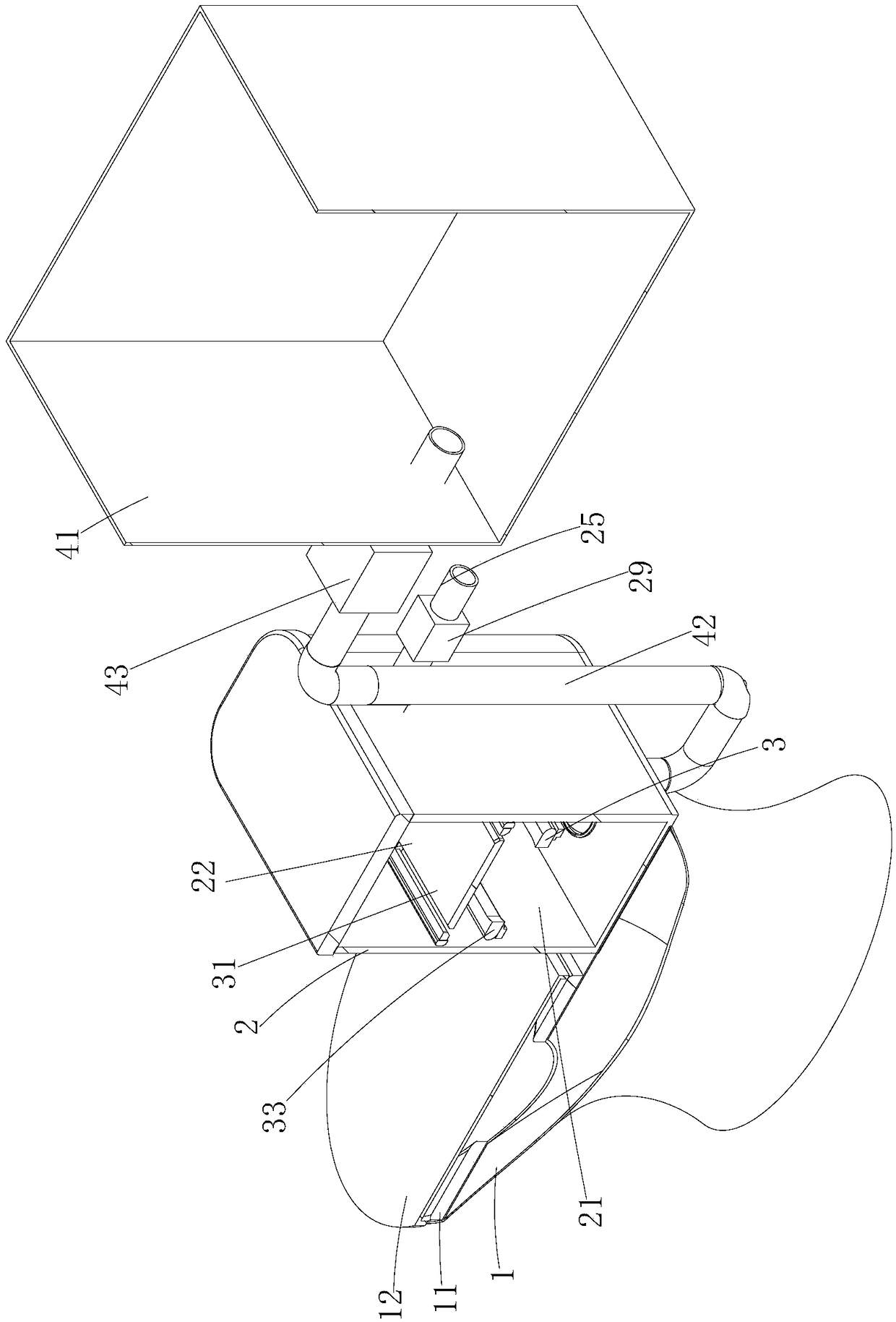
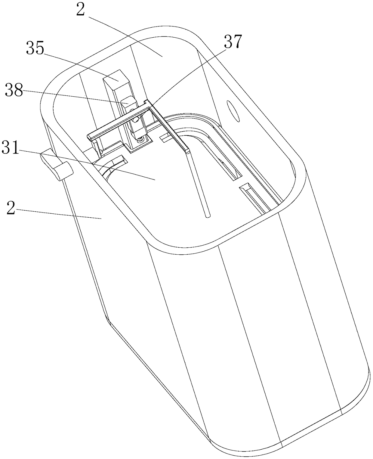
[0035] Such as Figure 1-11Shown, a kind of ultraviolet sterilizing toilet comprises the toilet cylinder 1 with edge on the upper part, the seat cushion 11 that is movably connected with toilet cylinder 1, the toilet lid 12 that is movably connected with described toilet cylinder 1, water tank 2, partition structure 3, storage Water structure 4 and ultraviolet disinfection structure 5, wherein said toilet bowl 1 is the toilet bowl of existing flush toilet on the market, and described seat cushion 11 is identical with the seat cushion of existing flush toilet on the market, and described toilet cover 12 is a plastic cover, The lower end surface of the toilet cover 12 is surrou...


PUM


Abstract

The invention discloses an ultraviolet light disinfection toilet. The ultraviolet light disinfection toilet comprises a toilet cylinder with an edge on the upper portion, a water tank connected with the toilet cylinder and a dividing structure used for dividing the water tank into a first water feeding cavity and a second water feeding cavity which are used for conveying domestic wastewater into the toilet cylinder, and the second water feeding cavity stores clear water and flushes the inner wall of the first water feeding cavity and the inner wall of the toilet cylinder after the domestic wastewater in the first water feeding cavity is discharged. The water tank of the ultraviolet light disinfection toilet is divided into the first water feeding cavity and the second water feeding cavity,the domestic wastewater is utilized, and therefore water resource waste is reduced; by arranging an ultraviolet light disinfection structure in a conveying pipe, the wastewater is disinfected instantly when used, the disinfection effect is good, bacteria are effectively prevented from breeding in the second water feeding cavity again, and it is guaranteed that the wastewater is in a sterile state.

Description

technical field [0001] The invention belongs to the technical field of daily necessities, in particular to an ultraviolet disinfection toilet. Background technique [0002] Ultraviolet disinfection technology has become more and more widely used in medical and health industries. It uses C-band ultraviolet light to generate strong ultraviolet C light to irradiate various bacteria, viruses, parasites and other pathogens on water, air or solid surfaces. When the ultraviolet C light radiation reaches a certain dose, the DNA structure in the cell is destroyed, thereby achieving the purpose of killing bacteria, viruses and parasites. [0003] In the existing market, ultraviolet light is mostly used on the toilet, and the ultraviolet C light is used to irradiate the toilet cover and other positions to sterilize the toilet cover, which has the effect of environmental protection and hygiene; Only clean tap water can be used for flushing, because the tap water has been disinfected an...

Claims


Application Information

Patent Timeline
Patent Type & Authority Applications(China)
IPC IPC(8): E03D11/06E03D5/00A61L2/10
CPCE03D11/06A61L2/10E03D5/003E03D5/006
Inventor 翁小佩李耀
Owner 杭州国瑞数码科技有限公司
Why Eureka
Try Eureka